This topic takes a closer look at the functions of the Group and Sector in predicting and monitoring the fallout situation. It should be read in conjunction with the overview of the Royal Observer Corps (ROC) in the Cold War period.
ROC Group and UKWMO Sector Bunkers
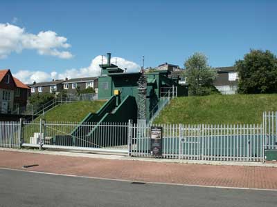
ROC Museum in York (former York UKWMO Group HQ)
During the period 1957-62 small underground chambers were constructed to protect the observer posts from blast and fallout. At the same time protected Group and Sector Headquarters were commissioned, mostly as purpose built semi-sunken bunkers, but Belfast and Bristol were converted redundant Anti-Aircraft Operations Rooms (AAOR) and former RAF bunkers converted at Inverness and Preston.
The picture shows the York Group HQ, semi-sunken to afford protection against minor blast damage and increase the fallout protection factor, now a museum operated by English Heritage. The bunker originally stood in the grounds of Shelley House, a Government building, when this was sold off and demolished for a housing development the external fence around the museum was added.
ROC Group Boundaries
This map shows the areas of the U.K. covered by the ROC Groups and each headquarters bunker shown as a dot.
Map of UKWMO Groups and Sectors
The table below shows the locations of all twenty five group headquarters in the UK. Five of the groups shown in bold letters acted as sector headquarters too, they are marked with green coloured dots on the map.
ROC Group & UKWMO Sector Locations
Sector Name
Grp
Code
Location
OS Grid
Lat/Lon
Metropolitan
1
MAI
Maidstone
TQ750561
51.275479, 0.508396
2
HOR
Horsham
TQ174303
51.059886, -0.325795
3
OXF
Oxford
SP551051
51.740829, -1.202682
4
COL
Colchester
TL985249
51.887335, 0.822912
14
WIN
Winchester
SU494310
51.076197, -1.310787
Midland
6
NOR
Norwich
TG236112
52.652889, 1.304433
7
BED
Bedford
TL028503
52.142067, -0.498842
8
COV
Coventry
SP457736
52.357767, -1.331806
15
LIN
Lincoln
TF046725
53.239000, -0.433769
20
YOR
York
SE580515
53.956851, -1.116820
Southern
9
YEO
Yeovil
ST551149
50.932714, -2.640723
10
EXE
Exeter
SX972960
50.754507, -3.458911
12
BRI
Bristol
ST716702
51.430669, -2.408887
13
SWA
Carmarthen
SN405198
51.854557, -4.318645
16
SHR
Shrewsbury
SJ499126
52.708531, -2.741573
Western
17
NWA
Wrexham
SJ358528
53.068130, -2.960850
21
PRE
Preston
SD539364
53.822388, -2.701133
22
CAR
Carlisle
NY383605
54.935025, -2.964314
23
DUR
Durham
NZ275429
54.780819, -1.574682
31
BEL
Belfast
IJ263658
54.524406, -6.048235
Caledonian
24
EDI
Edinburgh
NT159739
55.951525, -3.347294
25
AYR
Ayr
NS347244
55.485867, -4.615725
28
DUN
Dundee
NO438314
56.471445, -2.913399
29
ABE
Aberdeen
NJ905084
57.166394, -2.155177
30
INV
Inverness
NH683455
57.480854, -4.198189
The Latitude / Longitude coordinates can be entered into Google Maps or Bing Maps search box, which places a marker on the building or the space it occupied. This method is far more accurate than is possible using the 6-Figure OS Map reference which identifies a spot within 100 metres of the location, therefore can be very misleading.
The Function of ROC Group HQ
Every Group HQ had thirty to forty ROC monitoring posts within its control. Each collecting data from their post instruments and forwarding it to group for processing into bomb detonation locations and estimated yield. Using this information and the prevailing weather conditions the path of any fallout could be predicted. Radiation readings taken by posts would be used to monitor the path of fallout to confirm the predictions were correct or make adjustments to them.
Monitoring Post Instruments
Every post has a Ground Zero Indicator (GZI) camera, Bomb Power Indicator (BPI) and radiation Fixed Survey Meter (FSM). Some selected posts have basic metrological measuring instruments too, to enable group to make their own weather forecasts. A full description and copious photographs of all these instruments are in their own separate Chapter, this can be found in the top of page menu bar or the quick links at the end of this page.
A further illustrated Chapter describes in detail the post to group landline communication equipment. The master post in each cluster was also equipped with a radio link to group described in another Chapter.
Information Gathered by Monitoring Posts
Whenever a post's BPI detected a bomb pressure reading in excess of 2 kPa, the BPI reading would be immediately passed to group as a 'TOCSIN' message. The definition of 'TOCSIN' is interesting bearing in mind the motto of U.K.W.M.O. is 'Sound an Alarm': From Old French toquesain (modern tocsin), from Provençal tocasenh, from tocar 'strike, touch' + senh 'bell'. NOUN:2) A bell used to sound an alarm.
After a one minute delay following the last BPI reading, the GZI cassette papers are retrieved and the details of the spot(s) passed to control as a 'NUCLEAR BURST' message. The first sign of fallout would be passed as a 'FIRST FALLOUT' message. After this, radiation dose rates would be collected from posts on a regular cycle.
The Group operating procedures detailed how these various messages are processed onto forms, the forms are used locally to create plotting information and shared via the telegraph network, with other UKWMO Group and Sector controls. The local data combined with that received from other groups, creates a national picture, this is shared with user services such as Local Authority Emergency Centres, Regional Government Headquarters, Armed Forces Headquarters and Nuclear Reporting Cells.
Triangulation of the Bomb Ground Zero
The point under a nuclear bomb detonation is known as its Ground Zero (GZ). A term that has become well used in public since the World Trade Centre attack of September the Eleventh 2001. ROC Posts send in details of bomb detonations recorded by their GZI camera as a bearing to the nuclear fireball in degrees clockwise from North. Group would use a minimum of two of these bearings to triangulate the ground-zero of the bomb.
Triangulation of Ground Zero
Triangulation requires a map of the area with the ROC posts marked on it. In this example we use some of the posts in the York Group. If 22 Post determined the bearing to be 159°, using North as a reference the plotter could draw a line from the post at that angle. The detonation could have occurred anywhere along the line. A second bearing of 124° from 35 Post is plotted on the map and where the lines cross is the location of Ground Zero. This is called triangulation because it creates a triangle between 22 Post, 35 Post and ground zero.
Only two posts needed to have witnessed the fireball for a triangulation to determine the ground zero, but a third reading of 107° from 50 Post confirms the target as Hull Docks. The more posts that observe the fireball the greater the accuracy of the ground zero location. If a multi warhead weapon was used then more than one fireball may be recorded on the GZI camera. Plotting a line for each fireball from three or more posts will allow the ground zero for each warhead to be determined.
In the 21st Century this may seem primitive, however it was very quick and effective. The UKWMO was set up more than 10 years before pocket calculators came onto the market. A pencil and ruler is not affected by Electro Magnetic Pulse (EMP), does not require batteries and most certainly less prone to operator error. EMP can irreparably damage electronic devices.
Determining Bomb Burst Height
Nuclear weapons would have been detonated at different heights to suit the type of target. Detonation height is very important to the UKWMO in predicting fallout and damage. Air bursts create less fallout but a greater circle of damage than a ground burst. A ground burst causes a large crater but a smaller circle of damage. As the ground material and debris get sucked up into the mushroom cloud it creates a lot of radioactive fallout.
Once the ROC Group control had determined the ground zero by triangulation, the height of the detonation could be calculated using the GZI Camera's elevation data and spot size. If the fireball does not touch the ground it is known as an air burst. If it touches the ground it is a ground burst.
Air Burst Threshold Height
Bomb Power
Threshold feet
20 Kilotons
600
½ Megaton
2,200
1 Megaton
2,900
5 Megatons
5,400
10 Megatons
7,200
This table shows the height threshold for different nuclear bomb yields expressed in tons of TNT. Below this threshold height the fireball touches the ground. Anything above this height the weapon is regarded as an air burst.
The Hiroshima and Nagasaki bombs had a power of about 20 Kilotons, a 10 Megaton bomb is 500 times more powerful than these, but few targets would warrant a bomb so large. On 30th October 1961 the Soviet Union exploded a 50 Megaton bomb, but it never went into service. A full description is given in Wikipedia search for 'Tsar Bomba'.
AWDREY
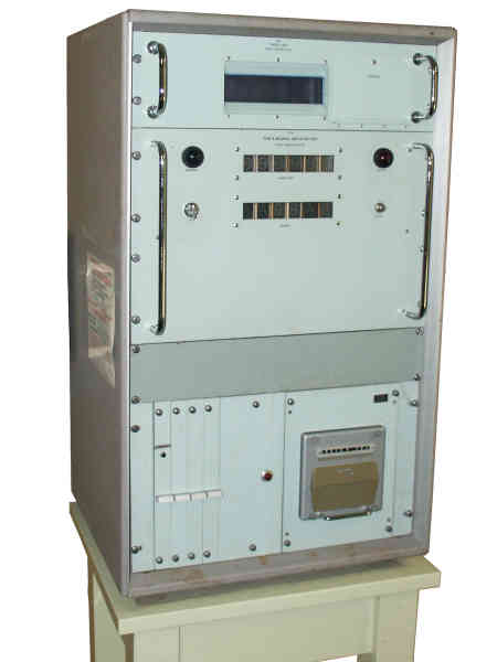
AWDREY Nuclear Burst Detector Display Unit
AWDREY the acronym for Atomic Weapon Detection Recognition and Estimation of Yield was designed and built by the U.K. Atomic Weapon Research Establishment at Aldermaston and went into service in 1968 at 13 of the 25 Royal Observer Corp (ROC) Group controls as an aid to determine the size of the bomb. Similar in design to a 'Bhangmeter' it uses an observed flash signature associated with nuclear weapons detonated below 30 km height. This signature consists of a short and intense flash lasting around 1 millisecond, followed by a second much more prolonged and less intense emission of light taking a fraction of a second to several seconds to build up. This signature, with a double intensity maximum, is characteristic of atmospheric nuclear explosions and is the result of the Earth atmosphere becoming opaque to visible light and transparent again as the explosion's shock wave travels through it.
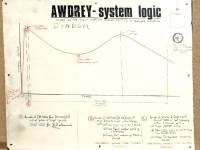
Awdrey Logic
A sensor head consisting of two banks of 5 solar cells is mounted on the roof of the bunker and connected to a main unit in the apparatus room which forwards the calculations to the display unit in the operations room. The electromagnetic and optical sensors were capable of detecting a nuclear burst over a 100km range. The circuitry was designed to detect the characteristic double flash of a nuclear bomb and record the time and direction. The intensity of the flash and electromagnetic pulse allows the size of the bomb (yield) to be estimated. The chart shows the signal characteristics of a nuclear weapon and the timing of the logic gates. Apparently it incorrectly recorded lightning flashes from thunderstorms as detonations.
Alerts from the AWDREY are entered on an 'Awdrey Data' form 'AA' and distributed nationally on the telegraph network. Also verbally announced in the Group control, using the format 'TOCSIN BANG' + Group Name + 6-figure time as indicated by AWDREY. For example 'TOCSIN BANG MAIDSTONE EIGHTEEN TWENTY FOUR OH EIGHT'
Nuclear Bomb Size
The peak overpressure reading measured by the Bomb Power Indicator (BPI) at monitoring posts in the vicinity of the nuclear burst are sent to Group. Once the location of Ground Zero has been triangulated, the posts' BPI readings can be used to estimate the yield of the bomb. Before the introduction of AWDREY this was the only means of estimating the bomb's yield.
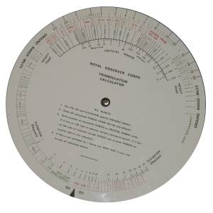
Bomb Size Calculator
This double sided plastic calculator is used to work out the yield size of the nuclear detonation. The rings are rotated to align the reported overpressure from the BPI, spot size from the GZI, range and elevation, as reported by the monitoring posts.
$
The user instructions are printed on the inner dial, these can be clearly read in the enlarged photograph. 'AB' refers to Air Burst and 'GB' to Ground Burst, variations in dial settings are required to obtain the correct estimation of yield for the different types of detonation.
Bomb Designation
Each bomb is allocated a designation letter used nationally to refer to the consequences of the detonation. The first bomb in York (YOR) Group would be 'YORA', second 'YORB'. The first in Lincoln (LIN) Group would be 'LINA', second 'LINB'. The time of detonation, location, burst type (Ground/Air) and yield are recorded for future reference and transferred to a form 'BB' then distributed nationally on the telegraph network.
Plotting Fallout
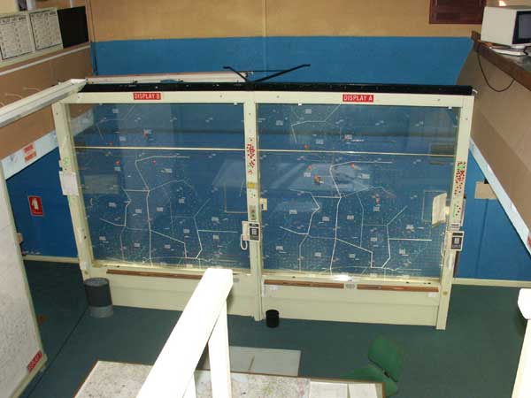
In Group and Sector controls, an illuminated plastic panel overlaid with a map is used to display the predicted and confirmed track of any radioactive fallout. A soft wax pencil, which could be wiped off, is used to draw on the rear of the panel. Once the yield of a ground burst weapon is determined, the known wind speed and direction are used to plot a predicted fallout path. The measured radiation readings supplied by the ROC posts are then used to confirm and refine the predicted path. Air burst weapons are recorded on the panel but no fallout predictions are made.
ROC Group HQ Display Screens
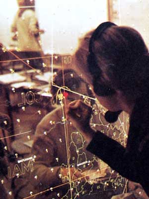
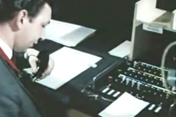
Here are the display panels at York Group HQ. The picture below from the UKWMO booklet shows the display panel being marked up from the reverse side with a plot of the fallout path. Red mushrooms indicate ground bursts that produce fallout and Green mushrooms for air bursts producing little or none.
Plotting Fallout on a Map of UK
UKWMO Warning Team
The responsibility for all threat assessments and their communication to the public resided with the UKWMO, the ROC played no part in this other than in a clerical capacity. Within the Group, the UKWMO warning team would attempt to predict the cone of fallout and the arrival time and plot this on a chart. Each Group Headquarters area was subdivided into Warning Districts. If fallout were imminent in a district a 'Fallout Warning BLACK' would be issued via the Carrier Control Point (CCP) for the affected district(s). Eventually the 'Attack Message White' or 'All Clear' would be issued via the CCP when fallout levels had decayed to a safe level.
Feedback - extract of an email from a former member of a UKWMO Warning Team
We (the Warning team members) were indeed a mixed bunch of scientists, engineers, ex military and lawyers, whose rather awesome job as volunteers (especially looking back on it) was to take the data generated by the ROC posts and staff around us, and turn it into real intelligence to predict what was going on 'out there' in terms of threat of fallout so that we could warn the public quickly and as accurately as possible. Our tool were weather forecasts, the bomb size, direction and type data from AWDREY, and predicted fallout patterns. As civilians, the warning team did not have to work under the same strictures as our uniformed colleagues, and we could see the farcical nature of some of our work. So the warning teams did what they could to try and practice warning the public — the whole point of the ROC network, whilst trying not to think of their families whom, one supposed, were being left to fend for themselves 'up top'. The debate on what would actually happen in the event never really developed, it was far too contentious.
Fallout Prediction - Warning Districts
Horsham Warning Districts Map
This portion of the plotting screen, shows part of the Horsham Group Control with the warning districts marked in Red. The little numbered dots are the ROC monitoring posts and the grid is the OS Map squares. The Green trumpet shaped area is the fallout from a ground burst bomb designated 'HORA' and marked with a Red mushroom in this exercise. The fallout progress is shown for various times in the fallout zone.
The Warning Switchboard Function
A special switchboard, the 'Warning Keyboard', was at the centre of another network of private circuits radiating out to the black telephone on Carrier Control Points (CCP) within the group's area. If fallout is expected in a warning district within the hour, the warning officer calls the CCP responsible for that warning district, requesting them to broadcast a Fallout 'BLACK' message over their carrier system. Later when the fallout has decayed, the All Clear 'WHITE' message is handled similarly.
As a contingency against the national attack warning system failing, group operating procedures included passing the 'RED' message to all their CCP if any bomb detonation had been detected prior to a red warning being received via the Group Control's own carrier receiver.
Warning Keyboard 1st Generation
The first generation switchboard uses a key and lamp arrangement. The Warning Officer throws a key to select the desired CCP within its area, then operates a call key. Incoming calls from the CCP light the lamp associated with the line and the Warning Officer operates the speak key on that line.
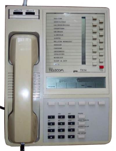
Warning Switchboard 2nd Generation
The second generation uses a TX14 Featurephone instead of a special switchboard. Its buttons are programmed with the four digit internal telephone number assigned to each CCP. This number can be dialled from any phone within the building, but only the Warning Officer's Featurephone has them preprogrammed on its buttons.
If a CCP calls the Group, the incoming call rings on this phone, but should it already be engaged on another call, the call transfers to another phone.
Monitored Radiation Levels
The private circuits from the monitoring post cluster's TeleTalk are terminated on the Post Display Plotter (PDP) desks who operate the tote board displays. One PDP handles two clusters of posts. Every even five minutes the PDP requests all the posts to pass their radiation readings. The tote boards are double sided so the PDP could update one side of the tote board then rotate it so the information was available for all to see whilst working on the next set of readings.
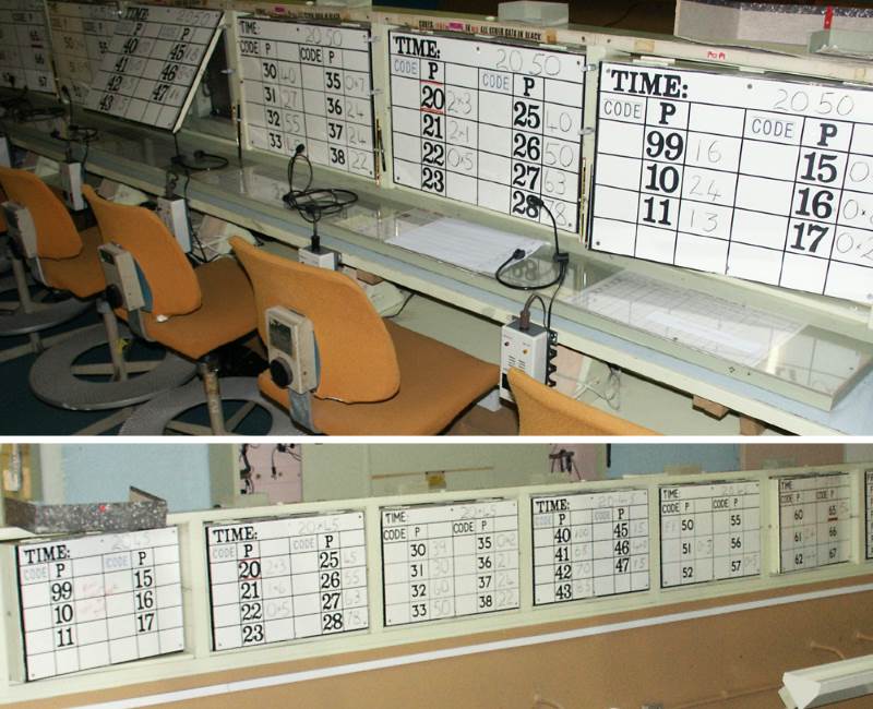
Both Sides of the Tote Boards
The lower image is the view of the tote boards as seen from the control room balcony. The time for the reading is written along the top of a tote board. Each board displays two clusters worth of information arranged in numerical order with the master post at the top of each column. The readings taken at this bunker are shown as Post 99. Each cluster is shown as three columns, the first is a code, the second the post number and the last the data. The code 'FF' with the time as data, indicates the time of arrival of the first fallout. The code 'CC' with a number as data shows the current radiation level at that post. Decimal points are shown as '3x6' for '3.6' otherwise the number is the reading in centi-greys. Other codes are 'PP' for post out of contact, replaced with 'QQ' for the first reading when it is back in contact. 'US' indicates the lack of radiation reading due to a faulty field survey meter. The data is visible to everyone in the control room to use for their task.
Sharing of Data
The bomb and fallout data is shared amongst all UKWMO Groups and Sectors in order to build up a national picture at each location. The UKWMO's function is to warn the general public but also very importantly, to share their data with other bodies. Fallout and damage predictions are shared with local and regional government to enable them to plan their relief work. Data was also shared with the armed services so they would know if it were safe to use their facilities or move around the country.
ROC Sector Headquarters Function
The Sector Headquarter were originally located at RAF Sector Operations Centres but were moved to be co-located with a Group Headquarter within the Sector. Sector Controls had some additional roles to perform. The Preston Sector had a set of equipment so they could issue the National Attack Warning via the HANDEL system should the UKWMO people at the Air Defence Operations Centre at Strike Command be unable to do so.
As we know from the accident at Chernobyl, nuclear fallout does not respect national boundaries so bombs aimed at targets in the UK could create fallout in Europe and vice versa. The UKWMO had Liaison Officers (LO) who were a small band of volunteers based in adjacent NATO neighbours to UK, two in each, 12 in all. There were LOs in Belgium, Norway, Denmark, Netherlands and France (two centres). Each NATO HQ was plugged into an adjacent Sector Control in UK. Belgium and France linked to Southern Sector in Horsham while the Midland Sector at Lincoln linked with Denmark and Netherlands.
Sectors had communication links from the Meteorological Office to receive weather forecasts. Should the Met Office be disabled there were direct links to selected upper air observation stations too. Combined with meteorological data from ROC posts a basic weather forecast could be produced at Sector.
Selected Groups or Sectors had links to RAF Radar stations. During a visit to the Neatishead Radar Museum I noticed a socket for the old link to Fiskerton which was the location of the ROC Midland Sector Headquarters at Lincoln.
Group and Sector Communications Overview
The Group and Sector HQs had an extensive communications network of its own. Other topics on this web site explore the communication network in great detail, use the menu to navigate. To summarise:-
A WB carrier receiver so it could receive the National Attack Warning to be aware of an imminent attack and go into lockdown mode. This is connected to the CCP serving the area where the Group bunker was physically located.
Each Group HQ has a communications centre for transferring messages to and from other Group HQ's. The centre allowed a single message to be broadcast to a number of other locations.
Group Headquarters were linked to the adjacent Headquarters by both landline and radio circuits carrying both speech and telegraph. Should a direct link fail or a message required to be passed to a Group that wasn't directly connected it would be relayed via another Group.
Each Group HQ had a landline and radio link to the Regional Government Headquarters (RGHQ).
A single sideband radio transceiver was provided for the Last Ditch Network (LDN) which could be used if all ground based communications (radio and line) were disrupted.
The five Sector Headquarters were additionally connected by land lines directly to the other Sector Headquarters. Sectors had links to their counterpart organisations in other European countries. Sectors had a BBC radio studio linked into the transmitter network.
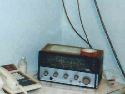
General Coverage Receiver
To enable group controls to listen to radio broadcasts from the UK and abroad, they were equipped with a general coverage receiver. This receiver tuned AM Long and Medium Wave, FM 88-108 MHz and AM short wave 1.5-22 MHz. But it didn't provide any SSB or CW reception.
Jim Went kindly contributed this photo taken on the last night the Shrewsbury control was manned, noting "The photograph of the logistics room (formerly known as the officers' room) with the Eddystone EB35 Mk.3 receiver on the table was taken by a fellow member of my crew who died over 20 years ago. I'm sorry it doesn't show the radio in detail."
 This page is Copyright © RINGBELL.CO.UK, under a