Home Defence Speech and Telegraph Network mid-1980s to 1992
This topic describes the changes to the original Home Defence communications network that took place during the mid-eighties. By this time the effects of the Electro-Magnetic Pulse induced by atomic weapons were understood and reflected into the design.
The Final Speech and Telegraph Networks
RGHQ and UKWMO Networks and their Interlink Points
This map shows the two core networks, the Emergency Communications Network (ECN) for Regional Government Headquarters, in orange and the other for the United Kingdom Warning and Monitoring Organisation (UKWMO) in green. The two are linked between the RGHQ to its UKWMO Group Control, shown in blue. The ECN is also connected down to Local Authority Emergency Centres (LAEC) and regional Armed Forces Headquarters (AFHQ). In the telegraph subsection further down this page, the extent of the network at County level will become apparent.
In this 2nd Generation network the main transmission links for both networks were carried on BT Landlines as they had been in the 1st generation. For the main core, landlines were provided with a radio backup by the Home Office Directorate of Telecommunications ( D-o-T ). Both the ECN and the UKWMO network began using the same radio bearer network known as Radio Network One (RN1) for the backbone and Radio Network Two (RN2) for the spurs to operational buildings. The 1st Generation radio networks, using VHF for the UKWMO and UHF for the Government Control Network (GCN) were recovered during the mid-eighties. It is unclear whether the replacement 2nd generation network on RN1 & RN2 was ever fully completed before stand-down in 1992. It certainly worked in some areas and if not others, even by 1990 there was a large hole in RN1, around the North West of England, without any radio equipment or aerials installed.
2nd Generation Telephony - The E.C.N.
The Government Emergency Communications Network (ECN) was introduced during the eighties. An extensive automatically switched network replaced the previous Government Control Network (GCN). A fragmented structure which often relied on the public telephone network to connect between the fragments. Now for the first time Police, Fire, Councils, Royal Observer Corps, Regional Government Headquarters, Armed Forces and Government departments were all connected to the same emergency network. It was managed by British Telecom for the Home Office Telecommunications Branch and operated separately from the normal public telephone communications systems. This provided a trunk dial facility for ECN telephone to call any other ECN telephone in any bunker across the whole of the UK.
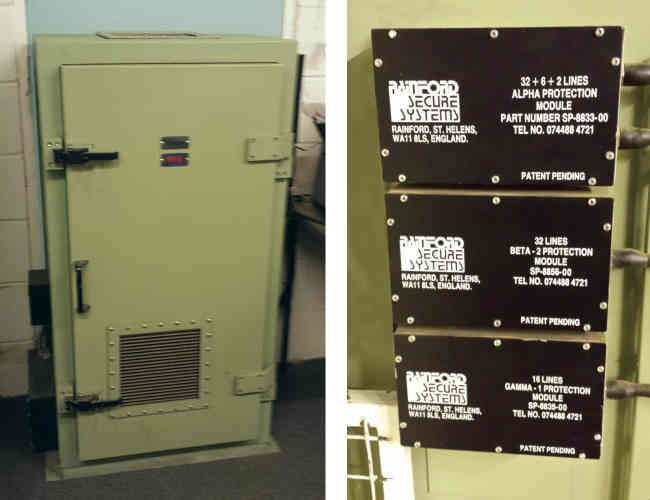
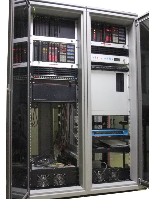
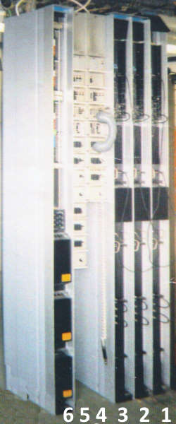
ECN Switch Cabinet - External NEMP Filters
Installation of the SX2000 switches for the UKWMO part of the ECN started in July 1988 and was completed by March 1989. After the UKWMO stand down in 1992 their part of the network closed leaving just the RGHQ part of the network until it too closed circa 1994. A restructured ECN continued to be used long after the closure of the RGHQs, see the topic "Post Cold War use of the ECN" on this page.
The photograph above shows a typical ECN exchange switch cabinet which houses the SX2000 switching unit. The switching units are duplicated to improve fault resilience. The lines into and out of the exchange pass through Nuclear Electro-Magnetic Pulse (NEMP) filters, mounted externally on the cabinet.
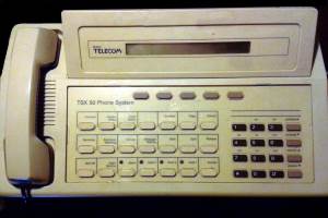
TSX50 Switchboard Operator's Console
A TSX50 unit was used when fewer extensions were required, such as at District Council controls. It has a capacity for up to 80 extensions, 24 exchange lines, 8 private circuits and has its own control console. The telephone instruments could be conventional desk or wall telephone (LD or MF4) as well as the TX14 featurephone.
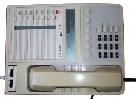
TX14 Featurephone
The switch would be installed in the Telecoms apparatus room in the bunker. In the office accommodation there would be an operators console to control the extension phones. If the console was not fitted the extensions could operate in 'Night Service' mode. Any extension on the ECN could directly dial any other in the UK.
Details of the TSX50 as used in the public network may be found on the website https://telephonesuk.org.uk/systems/, there are lots of photographs of the circuit boards.
The SX2000 is still in production but has been enhanced since the model featured here was installed as part of the ECN. This seems to describe the ECN version www.britishtelephones.com/sx2000s.htm
ECN Numbering Plan
A uniform numbering plan was adopted across the whole of the UK, allowing any ECN extension to call any other on the system. This facilitated the following arrangement. RGHQs and UKWMO Group HQs had 3 digit extension numbers, all other extensions had 4 digit numbers. To call the switchboard operator in your own bunker, key 100.
Internal Calls
To call any extension within your own RGHQ building, key the 3 digit extension number.
To call any extension within your own Group HQ building, key the 3 digit extension number.
To call any extension within your own Emergency Centre, key the 4 digit extension number.
External Calls.
To call a UKWMO Group, key the 3 digit group code followed by the 3 digit extension number. The group code is created by adding a 6 in front of group number; 608 = Coventry No.8, 612 = Bristol No.12
To call a RGHQ, key the 3 digit regional code followed by the 3 digit extension number. The Regional code is created by adding 5 in front of the RGHQ number; 531 = Skendleby 3.1, 592 = Drakelow 9.2
To call any County Council or District Council Emergency centre, key the 3 digit regional code followed by the 4 digit extension number. This Regional code is the same one for the RGHQ it comes under.
County Councils are allocated 100 four digit ECN extension numbers per Emergency Centre. The first digit being a 7, then within any one RGHQ zone, the second digit (x), starting from 0, is obtained by listing the counties alphabetically and assigning firstly the main and then the standby emergency centre. The switchboard would always be 7x00. To make it easy to contact generic functions in any council some numbers were predefined, so for example the County Controller would be 7x01. Scientific Advisers 7x04.
District Councils are allocated 25 four digit ECN extension numbers per Emergency Centre. The first digit being a 4, then within any one RGHQ zone, the remaining three digits (xyz), starting from 000, are incremented by 25 for each centre in an alphabetical list by County and District. e.g. 4000 - 24;4025 - 49;4050 - 74;4075 - 99;4100 - 24; etc. The lowest number at each emergency centre is the incoming number for the switchboard. Again a series of extension numbers were reserved for generic functions, but with a 25 number block it became a little more complicated, Scientific Advisers would be one of 4x04, 4x29, 4x54, 4x79 according to the first number in the block of twenty five.
The paragraphs above describe the numbering plan, the actual number of extension telephones fitted per emergency centre would be dictated by local circumstances and most likely well short of the ultimate capacity of the telephone switch. An example of the numbering scheme is tabled below.
Home Defence Region 3, ECN Number Ranges
Region 3 ECN Numbering Ranges
RGHQ 31
Skendleby, Lincolnshire
531 100-299
Derbyshire Main Emergency Centre
531 7000-99
Derbyshire Standy Emergency Centre
531 7100-99
Lincolnshire Main Emergency Centre
531 7200-99
Lincolnshire Standy Emergency Centre
531 7300-99
Nottinghamshire Main Emergency Centre
531 7400-99
Nottinghamshire Standy Emergency Centre
531 7500-99
Derbyshire
Amber Valley District Council
531 4000-24
Bolsover District Council
531 4025-49
Chesterfield District Council
531 4050-74
Dales District Council
531 4075-99
Derby City Council
531 4100-24
Erewash District Council
531 4125-49
High Peak District
531 4150-74
North East Derbyshire District Council
531 4175-99
South Derbyshire
531 4200-24
Lincolnshire
Boston District Council
531 4225-49
East Lindsey District Council
531 4250-74
Lincoln City District Council
531 4275-99
North Kesteven District Council
531 4300-24
South Holland District Council
531 4325-49
South Kesteven District Council
531 4350-74
West Lindsay District Council
531 4375-99
Nottinghamshire
Ashfield District Council
531 4400-24
Bassetlaw District Council
531 4425-49
Broxtowe District Council
531 4450-74
Gedling District Council
531 4475-99
Mansfield District Council
531 4500-24
Newark + Sherwood District Council
531 4525-49
Nottingham City Council
531 4550-74
Rushcliffe District Council
531 4575-99
RGHQ 32
Loughborough, Leicestershire
532 100-299
Leicestershire Main Emergency Centre
532 7000-99
Leicestershire Standy Emergency Centre
532 7100-99
Northamptonshire Main Emergency Centre
532 7200-99
Northamptonshire Standy Emergency Centre
532 7300-99
Leicestershire
Blaby District Council
532 4000-24
Charnwood District Council
532 4025-49
Harborough District Council
532 4050-74
Hinkley + Bosworth District Council
532 4075-99
Leicester City
532 4100-24
Melton District Council
532 4125-49
North West Leicestershire DC
532 4150-74
Oadby & Wigston District Council
532 4175-99
Rutland District Council
532 4200-24
Northamptonshire
Corby District Council
532 4225-49
Daventry District Council
532 4250-74
East Northamptonshire District Council
532 4275-99
Kettering District Council
532 4300-24
Northampton District Council
532 4325-49
South Northamptonshire District Council
532 4350-74
Wellingborough District Council
532 4375-99
2nd Generation MSX Telegraph Switch
Modern store and forward automatic switches similar to those in the civilian world replaced the old torn tape telegraph centres. All messages have a header as well as the text of the message, the header contains a routing code or addressing information that the switch recognises.
After an initial trial in Dundee UKWMO Group Headquarters the rollout of the 'Case MSX' message switch started at Maidstone and was completed with Belfast in June 1985. I have no detailed information about the RGHQ switch rollout. The MSX switch worked with Visual Display Units ( VDU ) and modern electronic teleprinters. These were much quicker and easier to use than the old mechanical teleprinters, paper tape perforators and torn tape centres used in the previous era.
Telegraph Message Switch Logic
The data switch is programmed with a routing table that determines for any particular routing code which of it's outgoing ports to send the message. There are three types of ports, those connected to other message switches in the network via landline or radio link through a Line Interface, ports to a Visual Display Unit (VDU) and ports to local printers.
As each node is connected to a limited number of nearby nodes, it is often necessary to route messages via a tandem node to get to the destination. If the message is destined for a recipient at a location without a direct link, the routing table contains the port number of a link going to a distant location, whose MSX can forward the message. It may be necessary to pass the message through a number of tandem MSX before it reaches the destination. In each switch, messages are stored in a queue and sent when the outgoing port becomes free. The message header will contain a Priority Indicator, showing the importance of the message, this governs where it is placed within the queue.
If the data link's land line or radio circuit connected to a port becomes faulty or is destroyed by enemy action, the system operator can divert all traffic from that port onto another working port, the messages will find a different path to their destination.
Outgoing messages were prepared using a VDU and sent to the destination, a local copy could be printed on the journal printer. The VDU operator can also perform management commands on the switching system, such as redirecting failed messages, adding and deleting routing codes. Incoming messages for recipients in the bunker are printed onto paper, to be delivered by hand.
MSX Message Switch Cabinets
Each function within the RGHQ & UKWMO telegraph network is allocated a short address code used in the message header to indicate the desired recipient(s). The message header may contain more than one address or one routing code can be used to broadcast a message to a number of destinations. This was clever stuff for 1980 and another 20 years would pass before EMAIL became commonplace - its what we know as an address list. One particular printer or VDU may be the destination for many routing codes. In EMAIL terms - having many email addresses drop into one Inbox.
The table shows a few examples of the Telegraph Network destination routing codes. A list of MSX codes are itemised in the Royal Observer Corp, Standard Operating Procedures, Annex AM. 'Identification Codes (Address of Units) including Multi-Address Codes'. The table gives examples of the format of codes for various kinds of users.
Breakdown of Code Types
RGHQ destination codes in England and Wales were three numbers made by padding the RGHQ number with zeros. Scotland and Northern Ireland Zones had a longer code. As well as the civilian part of the RGHQ, the Military liaison comcen had a separate code in the NATO range RBDxxx
Local Authority Emergency Controls have an identity made up of a three letter County code e.g. Gwent 'GWE' suffixed with 'MN' for the County Main Control and 'SB' for the County Standby Control, addressed as 'GWEMN' and GWESB' respectively. In counties with District controls, their address used the county code with a two letter suffix in the form of an abbreviation of the District Council name. Districts in Gwent, Monmouth 'GWEMO'; Newport 'GWENO'. County Police Headquarters routing codes followed a similar convention with a 'PO' suffix following the county code, 'GWEPO' for Gwent Police. County Fire Brigade Headquarters used a 'FB' suffix, 'GWEFB' for Gwent Fire.
All the UKWMO Group Controls have a suffix of 'WM' added to their Royal Observer Corp location three character code, e.g. 'BEDWM' for Bedford. The Group's admin address is 'ROC' and the Group number e.g. 'ROC07' for Bedford. The five UKWMO Sector Headquarters a three letter abbreviation of the Sector name, the METropolitan Sector at Horsham, along with CAL MID SOU WES to form a code like 'METWM'.
UKWMO Broadcasts
In addition to direct point to point codes, special broadcast codes were allocated to allow a single message to be sent at once to all recipients in a sector. These use 'MA' then a 2 character abbreviation for the sector name CL MT MD SU WS and a single digit. For example, addressing a message to MAMT2 would deliver it to all Groups, NRC and Local Authority Emergency Centres in the Metropolitan sector area.
Examples of Broadcast Codes for Non-Routine Messages
Code
Description
Sector Control to all Groups in their sector
MACL1
Caledonian Sector
MAMT1
Metropolitan Sector
MAMD1
Midland Sector
MASU1
Southern Sector
MAWS1
Western Sector
Sector Control to all Groups, NRCs and Customers in their sector
MACL2
Caledonian Sector
MAMT2
Metropolitan Sector
MAMD2
Midland Sector
MASU2
Southern Sector
MAWS2
Western Sector
Sector Control to all other Sector controls
MACL3
From CAL (Caledonian) to MET MID SOU WES
MAMT3
From MET (Metropolitan) to CAL MID SOU WES
MAMD3
From MID (Midland) to CAL MET SOU WES
MASU3
From SOU (Southern) to CAL MET MID WES
MAWS3
From WES (Western) to CAL MET MID SOU
UKWMO Routine Messages
During the attack and post-attack period, Group and Sector controls would originate many routine messages in a fixed format. Some message formats being copies of ROC's paper forms containing vital information. To facilitate sending these routine messages, broadcast codes in the format xxYYY were created, where xx was the form code and YYY the originating group or sector. For example BB (bomb burst) messages originate from Groups while TT (fallout threat) messages originate from Sectors. Two examples are shown in the Broadcast Code table.
Using an originator code as the destination address may seem strange, but it facilitates a way of directing messages only to those authorities that need to receive them. For example, fallout warning from groups are broadcast throughout the network but may only need to be printed at County emergency centres whose territory is part of that group. Leicestershire Emergency Centre, would need to receive messages from COV, BED and LIN, to cover the whole of the county.
Broadcast Codes for Routine Message Formats
Code
Description
Broadcast BB (Bomb Burst) Messages : One per Group, BBxxx
BBCOV
From Coventry
BBEXE
From Exeter
Broadcast TT (Fallout Threat) Messages, one per Sector TTyyy
TTSOU
From Southern Sector
TTWES
From Western Sector
Military Liaison In RGHQ
The U.K. Armed Forces routing codes begin 'RBD' these are a sub-set of NATO military routing codes used by all three services and our NATO allies, all those based in the UK are in the format RBDxxx.
The military were tasked in supporting the Regional Government and County Councils in the post-strike recovery phase by providing manpower and logistics. The MSX network extended beyond the civilian organisation to include the parts of the military who would provide that assistance.
Military Liaison at RGHQ Routing Codes
RGHQ No.
Location
Routing Code
RGHQ No.
Location
Routing Code
21
Shipton
RBDPAP
81
Colwyn Bay
RBDTVQ
22
Hexham
RBDPDA
82
Brackla
RBDTVS
31
Skendleby
RBDPAI
91
Swynnerton
RBDPKN
32
Loughborough
RBDPAV
92
Drakelow
RBDTWT
41
Bawburgh
RBDPDK
101
Southport
RBDPKP
42
Hertford
RBDPDM
102
Hack Green
RBDTVK
51
Kelvedon Hatch
RBDPDL
Scotland
61
Dover
RBDPFD
Central
Kirknewton
RBDPBQ
61
Crowborough
RBDTRX
North
Anstruther
RBDPAK
62
Basingstoke
RBDTVL
West
East Kilbride
RBDPAL
71
Ullenwood
RBDTVR
East
Barnton Quarry
RBDPAJ
71
Chilmark
RBDTRV
Northern Ireland
72
Hope Cove
RBDTRG
Central
Cookstown
RBDPKJ
Within each Home Defence Region, one Armed Forces Headquarters (AFHQ) served the Region and was linked into both the RGHQ and UKWMO telegraph networks and possessed its own routing code. In the case of Region 2 the code for its AFHQ is RBDAPM. The two RGHQs in each Region contained a room designated 'Military Liaison' containing military personnel and communication equipment. There were printers and telephones connected into the RGHQ network. Each Military Liaison office having its own separate routing code from that used by the Civilian part of the RGHQ. At Shipton the Civilian routing address is 021 and its military counterpart RBDPAP.
Armed Forces HQ
Armed Forces Headquarters ( AFHQ ) were also linked into the MSX network. The list below is a snapshot derived from the ROC Standard Operating Procedure, Annex AM. Anyone who has studied UK military history will appreciate it seems to be an endless set of reorganisations, every document I see has a different set of codes reflecting the snapshot in time when the document was written. The ECN Directory has a similar set of codes with a few variations. The locations are derived from a Declassified Joint Signalling Instruction, where the codes match. Some physical locations of codes in this list are currently unknown.
AFHQ Routing Codes in Annex AM
Regional AFHQ
Routing Code
Location
2
RBDAPM
?
3
RBDPEG
Digby
4
RBDPKT
5
RBDPEK
Beaconsfield
6
RBDAPD
?
7
RBDAPE
?
8
RBDAPF
?
9
RBDTOE
Shawbury
10
RBDAPO
?
N.I.
RBDPKJ
?
Scot
RBDPBJ
Inverbervie
Additionally, the military had their own private automatic telegraph network 'Telegraph Automatic Switching System' ( TASS ) working in a similar way the to the now defunct UK Public Telex network but with four digit numbers. Lines from this network terminated in the RGHQ military liaison offices.
Message Format
Message exchanges operated by humans, such as the Torn Tape Relay centres are fairly tolerant of messages that don't conform to the specified formats. For example if the recipients address is invalid because the clerk has typed 'COVMW' instead of 'COVWM' they can easily make the correction and pass it to the correct destination.
Computerised message exchanges are unable to tolerate even the slightest mis-formatting. It was planned that county controls would compose their messages on a teleprinter and then send it off to the RGHQ message switch but it was found to create lots of work for the switch supervisors to correct the message format. Smaller message switches were rolled out to county and district controls so they could use a Visual Display Unit (VDU) to enforce the correct format.
RGHQ / Council Messages and ROC Non-Routine Messages
These free format messages adopted the protocol used by the UK Military and NATO, known as the 16 line message format although not confined to 16 lines, as the message itself may take up a variable number of lines. Dependant on the message type certain of the 16 lines may not be required.
UKWMO Fixed Format Routine Messages
Many fixed format messages are broadcast around the network from the Warning and Monitoring part of the organisation. These are composed on VDU's in the UKWMO Group or Sector Headquarters and their format reflects the paper forms used to prepare the data, in general the text of the form is not sent but only the data. There are 19 formats used by Groups and a further 6 by Sectors The example here is a message informing customers of a nuclear bomb detonation in France, a Bomb Burst BX form is used.
Form BX Example
2nd Generation County Telegraph Network
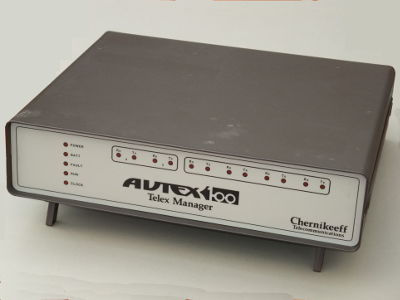
The 'Case MSX' telegraph switches were used in the RGHQ and UKWMO Control bunkers, but in Local Authority Emergency Controls (LAEC) a smaller capacity switch was needed, the 'Autex 1600 Telex Manager' made by 'Chernikeef Telecommunications' having a maximum of 24 ports was used instead. This was fitted with 4 megabytes of RAM memory and a connection for a portable disk drive.
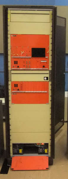
County Message Switch Arrangement
As the Autex 1600 has only a single processor, a backup 'Autex 100 Telex Manager' with just 5 ports and 128 Kilobytes of memory, allowed a very minimum service to be maintained in the event of a failure of the main Autex 1600 switch. Only two external links are provided to the backup Autex 100, one to the RGHQ and the other linking the Main LAEC to the Standby LAEC. One VDU and two printers are supported by the backup switch. Both the main and backup message switches are mounted in the same rack.
Standardised Autex 1600 Port Allocation
Port
Allocation
00
Journal Printer
01
Incoming Message Printer A
02
Incoming Message Printer B
03
VDU A
04
VDU B (spare)
05
Line data link to UKWMO Group Control
06
Line data link to RGHQ/ZONE
07
Radio data link to RGHQ/ZONE
08
Line data link between Main & Standby
09
Line data link to Police HQ (Main only)
10 ... 22
Line data links to Districts as required by the Local Authority to a maximum of 13 District controls
23 24
Input from a portable Disk Drive
A standardised configuration of ports on the Autex 1600 switch was adopted as shown in the table, for the County Main and Standby LAEC. Flexibility in the use of ports 10 to 22 allowed for Counties with a number of district controls. Note the connection to the RGHQ or Scottish Zone HQ, has two data links, one by landline and the other over the radio circuit. The installation consisted of three Siemens PT85 printers and two Zentec ADM3E Visual Display Unit (VDU).
Backup Autex 100 Standardised Port Allocation
Port
Allocation
00
Journal Printer
01
VDU A
02
SCVF data link to RGHQ/ZONE
03
SCVF data link between Main & Standby
04
Incoming Message Printer A
The changeover switch allows one VDU and two printers to be switched from the Autex 1600 to the standby Autex 100. It was also necessary to unplug two Autex 1600 leads from the line jack units on the landlines serving the RGHQ / ZONE and the circuit linking the Main and Standby centre, then plugging in the Autex 100 leads in their place. Normally the Autex 1600 at the County Standby centre has its ports closed so they do not forward messages. This is necessary otherwise the districts would receive four copies of each broadcast message. If the Autex 1600 at the County Main LAEC fails and they switch to the Autex 100, the County Standby LAEC must opens its ports to allow messages to route through it to the districts.
Switching from Normal Autex 1600 to Autex 100
District Councils & County Police HQ
Autex 100 at District level Standardised Port Allocation
Port
Allocation
00
Journal Printer
01
VDU A
02
SCVF data link to Main LAEC
03
SCVF data link to Standby LAEC
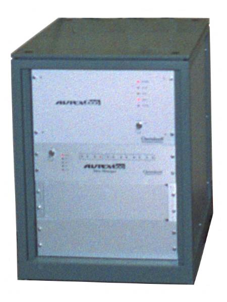
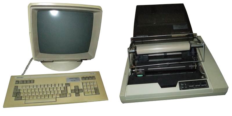
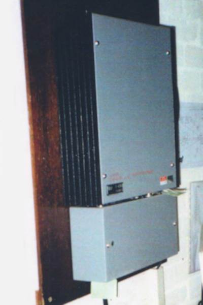
District council controls and county police headquarters were fitted with a 'Chernikeef Telecommunications, Autex 100 Telex Manager' having only 4 ports and 64 Kilobytes of memory, like the one shown in the gallery. These small units connected into the national telegraph network via the switches in the county's Main and Standby LAEC. The unit has two Single Channel Voice Frequency Telegraph (SCVFT) modem cards for the external line connections to the Main and Standby LAEC, the rear panel houses D-Type connectors for a single MT80 printer and a dual purpose Zentec ADM3E. This VDU would be used to prepare outgoing messages as well as manage the switch's supervisory functions. Most commands don't require the entry of the system password 'AYLTH'.
4 Port Autex 100 Telex Manager
The AUTEX 100 switches used at District level and Police HQ's also have a standardised port allocation for their four ports to ease with network administration. The Police HQ only has a single data link to the County Main LAEC therefore the port to the Standby is not used.
Zentec ADM3E Screen and Mannesman Tally MT80
SCVF Telegraph Links
The WWII Defence Telegraph Network and from its inception the public Telex network used electromechanical teleprinters transmitting at 50 bauds by plus and minus 80 volts signals. The public Telex exchanges were also electromechanical using similar 'Strowger' selectors to those used in the automatic telephone network.
During the seventies the Telex exchanges were being modernised with computer controlled systems. While the use of +/- 80 volt signals suited electromechanical exchanges, they were not suited to low voltages found in the modern systems. Likewise mechanical teleprinters were restricted in their speed to 50 bauds in the UK. Computer controlled exchanges could handle a much faster data rate.
In parallel with the modernisation of exchanges, the teleprinters themselves were becoming computer controlled and using dot matrix printing capable of a faster throughput than 50 bauds.
Alongside this modernisation, a new way of connecting Telex terminals to their exchanges was adopted. The UK's Single Channel Voice Frequency (SCVF) telegraph modem was adopted to replace the +/- 80 volt systems. This very simple modem was based on the International Telecommunications Union (ITU) recommendation R.20, which specifies the characteristics of its operation. Recommendation S.3 specifies the operation using Start / Stop data, rather than the synchronous data we now associate with computer interfaces.
The Telex network defines channel 1 to be in the direction of exchange to customer with channel 2 from customer to exchange. In the 2nd Generation Civil Defence network, the SCVF generally worked at 50, 75, 100 and 300 bauds. As this network connects message switches together, the concept of exchange and terminal used in the Telex network doesn't apply. But is is essential that either end of the private wire has a different modem configuration.
With reference to the AUTEX message switches at LAEC, the RGHQ links are configured as "Master" at both Main and Standby. The link between the Main and Standby, has the Main configured as "Master" and therefore the Standby is configured as "Slave".
SCVF Transmission Frequencies [V21]
Circuit End
FA Space Start 0
FZ Mark Stop 1
Channel 1 / Master
1180 Hz
980 Hz
Channel 2 / Slave
1850 Hz
1650 Hz
Typical County Network
Civil Defence Telegraph Network at County Level
This drawing centred on Oxfordshire, shows the connections between the various controls and two adjacent Counties. The message routing codes are shown (in Green) for each node. The RGHQ at Basingstoke (RGHQ 6.2) also has links to the main and standby controls in Hampshire and the Isle of White, also to Winchester UKWMO Group Headquarters and AFHQ for Region 6, omitted for clarity.
Basingstoke was connected into the RGHQ core network with links to Hertford: 4.2, Kelvedon Hatch: 5.1, Crowborough: 6.1, Chilmark 7.1, Swynnerton: 9.1
The UKWMO Oxford Group Headquarters at the ROC No.3 Group at Cowley had links into the UKWMO core network with connections to Bedford, Bristol, Coventry, Horsham, Shrewsbury, Winchester and Yeovil.
Using this example of a small area it can be seen that the Civil Defence telegraph network in the UK was very extensive. Telegraph messages could be passed between any node throughout the countrywide network. Should links within the network be broken due to enemy action the messages could be rerouted via working sections.
$
2nd Generation Radio Networks RN1 and RN2
During the later part of the eighties the emergency services were required to change their main operating frequencies to comply with newly introduced World Administrative Radio Council ( WARC ) rules. This period also heralded the introduction of a new radio scheme for the UKWMO and RGHQ network. This network moved away from the older single circuit per carrier at VHF and UHF frequencies towards a Microwave backbone with spurs to user's bunkers.
Description of Network
The Home Office Department of Telecommunications, Technical Engineering Instructions ( TEI ) have the following introduction describing the network.
          RN1/RN2  is an integrated radio communications  network
which is designed to carry ECN and UKWMO circuits.

          RN1   provides  up  to  24  channels  multiplexed  onto
microwave  radio  bearers  which link  hilltop  sites  throughout
England and Wales. The RN1 network is linked to a similar network
in Scotland which is controlled by the Scottish Office. A further
link  is  provided  from  the Scottish network to  a  network  in
Northern Ireland.

          RN2 provides single and multi channel links between the
user  and  the RN1 microwave network.  RN2 also  provides  direct
radio  communication  links   between   users  premises,  without
recourse to the RN1 network, where workable radio paths exist.

          The  RN1/RN2   radio  is   designed  to  provide   full
duplex speech and telegraph channels between users similar to the
service   already   provided  by  land  line   thereby   offering
alternative communications paths.
RN1 and RN2 Detailed Structure
The new national radio network consisted of a highway designated RN1 and spurs to users bunkers designated as RN2. RN1 was a high capacity radio network where lots of individual circuits could be combined on to one radio system operating at microwave frequencies. RN2 was similar but with lower capacity links to RGHQ or UKWMO ROC Group HQ operating at either UHF or microwave frequencies. Smaller bunkers, such as Local Authority Emergency Centres had one or more RN2 single channel links. Both RN1 and RN2 high capacity links used Frequency Division Multiplex, a technique also used on landlines since the 1930s to cram a number of speech circuits onto one bearer. Speech Multiplex is described in a separate topic on this website.
RN1 Spine Radio Network
This diagram shows the extent of the RN1 spine network passing between hilltop radio sites and including six RGHQ bunkers and two UKWMO Group HQs too. All the other user locations were connected into the spine by RN2 links. The individual circuits are cross connected between multiplexes at the hilltop sites in order to achieve a point to point link spanning between bunkers. To allow circuits to take a diverse routing, some of the multiplexed links in RN1 were formed into a ring allowing some circuits to route in either direction around the ring. Multiplexes varied in size, with 8, 12 and 24 channels, depending on the capacity needed in that section of the RN1 network.
The RN1 network diagram is only a small part of the story and doesn't show which circuits were carried on individual RN1 links. The RN2 network must have been quite extensive considering how many locations had to be connected, but I have very little specific information on the RN2 part of the network. Probably the majority of Home Office hilltop sites were used to convey RN2 links to bunkers. Any feedback via the home page would be most welcome.
Radio Link Equipment
The spine of the RN1 network utilises Pye L700 analogue microwave multiplex. Racks 1,2 & 3 are the microwave transmitter and receiver equipment, known as a transceiver, as this site is a tee in the RN1 network there are three transceivers, one for each direction, but those on the main spine have just two.
Rack 4 is the multiplex for the transceiver in Rack 1, with Rack 5 containing two multiplex for the other transceivers in Rack 2 & 3. The upper half of Rack 6 contains the connection blocks terminating the analogue circuits in and out of the multiplex. The lower section has the three power supplies for the transceivers.
Pye L700 for RN1
The multiplex takes the incoming baseband signal from the L700 receive section and breaks it down into 12 or 24 individual analogue speech channels. The multiplex also combines the outgoing speech from those channels into a baseband signal to feed into the transmitter section of the L700.
Each individual channel comprises of a standard interface of eight wires. Four wire speech has a pair for received speech, a pair for transmitted speech. Then four more wires for E & M signalling. E wire pair carries the signalling from the distant end, that was relayed over the radio system as a 3825 Hz tone. The M wire pair takes signalling towards the distant end, into the multiplex to be converted into a 3825 Hz tone. The use of this standard interface allows circuits to be through connected along the RN1 spine or to branch off onto RN2 spurs.
Plessey PRD100 for RN2
The Plessey PRD 1100 Multiplex for the RN2 network carries 8 or 12 multiplexed speech channels in the UHF bands. These high capacity spurs generally serve the majority of UKWMO Group HQ or RGHQ that are not RN1 sites themselves.
Like the L700, the PRD1100 analogue channel interface is the standard 8 wires. Enabling it to cross connect with RN1 and any other RN2 spurs.
A detailed explanation of speech multiplexing used in the L700 and PRD1100 is provided in a separate chapter on this website. Found in the Miscellaneous Topics part of the Chapter Menu.
Pye F496 for RN2
Local Authority Emergency Centres (LAEC), typically have only a backup radio path for the landline to their RGHQ. For this single circuit a wall mounted Pye F496 is used at the LAEC. At the hilltop site, the F496 is rack mounted.
The F496 radio is very versatile, and may be configured for the standard eight wire interface. For connection to the ECN telephone system at the LAEC, it may be configured for 2 wire audio, with a single pair carrying speech in both directions, instead of the four wire transmit pair and receive pair. The radio is normally mains powered but has the ability to have a standby battery supply too.
RN2 Intermediate Hilltop Repeater Schematic
The LAEC may be some distance from the RGHQ or RN1 spine and require the use of one or more intermediate hilltop sites to gain access to it. The simplified diagram above, shows the connection of two Pye F496 back to back for a through link at a hilltop.
The pair of wires carrying the receiver audio from one direction is connected to the transmitter in the other direction. Similarly for the returning audio path. The transmitters operate continually whether or not the circuit is in use, by permanently connecting the 'Key Transmitter' input to ground. Signalling is transferred over the radio path by a 3825Hz tone, the oscillator (Osc.) is turned on when necessary, by a signal on the 'M' signalling pair. The receiver contains a filter to block the signalling tone from appearing on the receive audio pair. The detector (Det.) recognises the 3825Hz tone and places a signal on the 'E' pair of wires. In this back to back arrangement, the 'E' pair of one transceiver is connected to the 'M' pair on the opposite side.
Pye DLM1, Dual Channel Combiner
The PRD1100 is used on medium capacity links in the RN2 network, but its expense is not justified for only a couple of circuits over a link. In this situation, a Pye DLM1 may be used at each end of a link to carry two separate circuits over a single radio path.
Speech on Channel 1 is carried in both directions at normal audio frequencies. Speech on Channel 2, is modulated with 8kHz and the lower sideband from 4 - 8 kHz is selected. The two channels are combined to feed the transmitter (TX) of the 'Radio Interface' with audio frequencies in the range 300 - 7,700 Hz. The received signal (RX) from the 'Radio Interface' is fed into both the channels. The voice frequency unit in Channel 1 filtering out the frequencies above 4 kHz. The modulator / demodulator circuit in Channel 2, firstly filters out the frequencies below 4 kHz and then demodulating those higher frequencies back into normal speech.
Signalling on both channels is accomplished using the standard 3825Hz tone. In the case of channel two, it is modulated along with the speech and appears at the 'Radio Interface' as a 8000 − 3825 = 4175Hz tone.
Both channel 1 & 2 connections have the standard eight wire interface, transmit speech pair, receive speech pair, signalling 'E' pair and 'M' pair. This allows it to be connected to either radio circuits going off in different directions or two ports in the ECN telephone system.
RN1 & RN2 Network Diagrams
The gallery of 'RN2 & RN2 Network Diagrams', shows the arrangement in Cornwall, of RN2 from the two LAEC, which utilise both back to back linking at Four Lanes hilltop and two circuits being carried over one radio path between the RGHQ 7.2 at Hope Cove and Hensbarrow Down hilltop site, using a DLM1 at each end. Also RN2 in the London Boroughs and the links radiating from Brown Clee hilltop.
Radio Frequency Allocations for RN1 and RN2
The 1979 World Administrative Radio Conference (WARC79) required changes in the UK to remove the Home Office frequency allocations for Emergency Services at 97.6 - 102.2 MHz and use this for Public Broadcast services. The United Kingdom's FM broadcast band then became aligned with our European neighbours extending from 87.5 to 108 MHz.
The emergency services vacating 97.6 - 102.2 MHz moved into the existing 146 - 148 MHz and 154 - 156 MHz frequency assignment, which was increased by the addition of 143 - 144 MHz and 152 - 153 MHz. The subbands 147.000 - 147.300 MHz paired with 155.000 - 155.300 MHz previously used for the ROC inter - Group HQ Network were withdrawn and reassigned for Emergency Service use. The resulting exclusive emergency service VHF bands became 143 - 148 and 152 - 156 MHz. Additional VHF allocations of 70.5 - 71.5 and 80.0 - 81.5 MHz were added for Fire Brigade and Royal Observer Corp Monitoring Post RN4 communications. At the same time the UHF allocations were expanded in size by adding 450 - 451 and 464 - 465 MHz, resulting in a combined UKWMO, police and prison service personal radio bands of 450 - 453 paired with 464 - 467 MHz.
The exclusive Civil Defence VHF band 168.325 - 168.800 MHz paired with 174.025 - 174.500 MHz was retained for use by Monitoring Post RN4 links from hilltop repeaters to their Group HQ. The UHF frequencies used for Regional Government links within the Emergency Service UHF band retained their allocation 452.000 - 452.225 MHz paired with 466.000 - 466.225 MHz along with the exclusive Civil Defence UHF band 455.875 - 456.000 MHz paired with 469.875 - 470.000 MHz continued to be used.
UHF Frequencies allocated for UKWMO and RGHQ Network
Shared UHF Band Channel Pairs
Exclusive UHF Band Channel Pairs
452.000
466.000
455.8875
469.8875
452.025
466.025
455.9125
469.9125
452.050
466.050
455.9375
469.9375
452.075
466.075
455.9625
469.9625
452.100
466.100
455.9875
469.9875
452.125
466.125
452.150
466.150
452.175
466.175
452.200
466.200
452.225
466.225
Two frequency assignments, 2 Megahertz wide separated by 30 MHz were allocated for RN1 and RN2 high capacity links at 1668 - 1670 MHz and 1698 - 1700 MHz, as they needed a greater bandwidth than was available on the lower UHF channels.
Aerial Systems
Shrouded Yagi Aerial for RN1
The spine of the Radio Network RN1 was carried on microwave shrouded yagi aerials as they were thought to be more resilient to the effects of a nuclear blast pressure wave than dish aerials, a 1.2 m (4ft.) dish would be required to achieve a similar aerial gain. The shrouded yagi weight is 4 kg with a wind load of 19 kg at 160 kph. a dish would weigh 40 - 50 kg with a wind load around 400 kg.
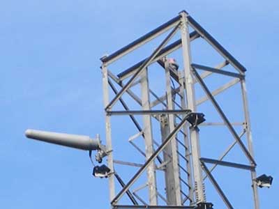
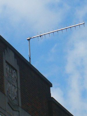
UHF 12 Element Yagi ( 450-470MHz )
Most RN2 access spurs from the RN1 spine to the control bunkers used either single channel per carrier or multiplexed operating at UHF frequencies. A UHF link whether it be for single channel or a multiplexed system would use a 12 element yagi aerial similar to the one shown above fixed to my local council premises. These antenna were used on home office hilltops sites too.
RN3 Onsite Security
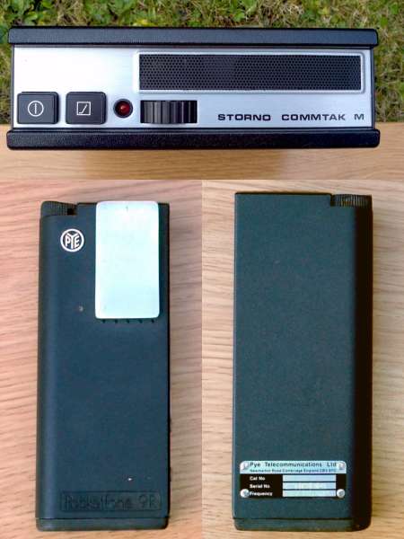
RN3 Radios
The onsite security at Belfast UKWMO Group Headquarters, consisted of a pair of Pye PF9 Pocketfones working into a Storno CQM 5662 base station, running 5 watts into a Jaybeam UHF folded dipole. These worked on Home Office Channel 13 (451.475 MHz Tx / Rx) allowing all three units to communicate with one another.
As well as Belfast No.31 Group, RN3 was installed at Maidstone No.1 Group, Shrewsbury No.16 Group, Preston No.21 Sector, Carlisle No.22 Group. Many others had it fitted too, although it is confirmed that Coventry No.8 didn't have RN3.
It would be interesting to know if similar arrangements were used at Regional Government Headquarters too ?
$
Post Cold War use of the ECN
At the end of the Cold War, the telephony part of the network continued to exist for another fifteen years or so. In 1999 it was made fully ready should the millennium bug hit, disrupting the public telephone network. A government letter dated 10 August 2006, advises of the decommissioning during the following 12-15 months. This would suggest final closure around the end of 2008. A Cabinet Office Freedom of Information request FOI320131 quotes an earlier decommissioning date of 2005.
Post RGHQ Network circa 2000
After the 1992 closure of the UKWMO and RGHQs the telegraph network of the ECN was closed as FAX machines and data modems were being employed instead. The telephony network was rearranged, moving top tier switches from RGHQs to new locations around the UK and linking them together with 2 Megabit digital links. The new switch locations with their former RGHQ zone numbers in square brackets were: Civil Defence College at Easingwold [21]. Six police training colleges at Durham [22]; Ryton in Dunsmore [31, 32, 91, 92]; Ashford [61]; Bramshill, Basingstoke [62]; Cwmbran [81, 82]; Bruche, Warrington [101, 102]; Police HQ at Halesworth [41, 42] Home Office, Queen Anne's Gate [51], The former Yeovil ROC Group HQ which had closed 31.12.1973 as part of the ROC rationalisation plan [71, 72].
Three fully interconnected switches were located in Scotland. One at The Scottish Office, Edinburgh, the interconnection point to England. The other two at Inverness and Comrie.
Top tier nodes acted as tandem switches as only adjacent nodes were directly connected to each other, shown by the black lines in this diagram representing 2 Megabit / 30 speech channel links. The numbering scheme for the counties remained unchanged from the cold war period.
For the first time, a bridge was introduced giving access to the ECN from the public telephone network. A national number allocated to each top tier switch could be dialled, when ringing tone changed to dialling tone, a pass code was entered, if this was correct, dial tone returned and the required full ECN number was keyed in. There was also a bridge from most top tier nodes into the Army Telephone Network (ATN). Other bridges were in place to and from the mobile phone networks using short codes and to the RAF Fixed Telecoms Network (RAFFTN). Local authority switches were given outgoing access to the public telephone network, a departure from the Cold War when the ECN was a completely separate entity.
The RN1 radio network protecting the landline network was also rearranged to feed the new switch locations and the RN2 spurs removed. RN1 had only routed directly through two UKWMO Group HQ at Carlisle and Bristol (Lansdown). At Carlisle the Northbound circuits were directly connected through to the Southbound ones.

 This page is Copyright © RINGBELL.CO.UK, under a