Royal Observer Corp Monitoring Post Radio Communications
This topic investigates the development of ROC Posts communications systems. Mapping the step changes in the master post radio scheme from its inception to stand down. For the first 10 years of their life, posts relied solely on landlines. Not all groups had the first generation of radios, some having to wait until the mid-eighties for the second generation to roll out.
1st Generation Group HQ to Master Posts by Radio
As a standby to the line communications between the cluster and Group HQ, the master post in each cluster was equipped with a VHF wireless set, to guard against failure of the landline. One post at least in the cluster could still pass its readings to Group. If the fault only affected the line between the cluster teeing point and the Group HQ, some or all of the posts within the cluster may still be able to talk to one another. If this happened, the master post would collect readings from the other posts in the cluster and relay these to Group HQ.
The group to post radios were operated in dual frequency simplex mode. All the master post radios would listen to the hilltop sites on one frequency and transmit back to the hilltop on another frequency. Due to this frequency split the posts could not directly speak to one another. This was the same technique employed on the Police and Fire in their countywide networks. Due to how the radio links were configured, posts in some groups may have been able to speak to one another via a hilltop and hear the traffic to group.
Post Radio, Plessey / AT&E Countryman 700
The master posts used an 'ATE Countryman' or 'Country Set' ATE 700, a battery operated thermionic valve wireless. Plessey purchased Automatic Telephones and Electric Co. ( ATE ), so some posts radio sets may have been badged as 'Plessey ATE 707'. Others may have had a 'Marconi / GEC RC 530 H' radio.
1st Generation ROC Post Radio Scheme Example
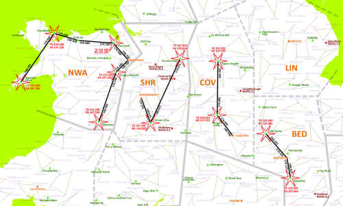
Due to the limited range of the posts VHF radios, Home Office hilltop sites relayed the signals to and from group headquarters via VHF radio links. The diagram shows the actual frequencies used by Shrewsbury (PINK) and Coventry (SKY BLUE) Groups and their respective hilltop repeater locations.
There was no direct communication between posts and group, everything went via hilltop repeaters. When group transmits it is received at the first hilltop and rebroadcast out on the post's radio channel as well as being retransmitted by its link transmitter. The second hilltop receives the link frequency and rebroadcasts the group's message on the post's radio receive channel. When a post transmits, it is received at one of the hilltops depending on its location. Taking the case of the second hilltop, it retransmits the post on its link frequency, which is received at the first hilltop which retransmits it on its link frequency. This link frequency is received by group.
As only two link frequencies are used, when a post within range of the first hilltop speaks to group, the message is also rebroadcast to posts by the second hilltop. Likewise, when a post within range of the second hilltop speaks to group, the message is rebroadcast on the post's receive frequency as it passes through the first hilltop.
Group Coverage Radio Schemes$
The gallery above shows a number of the Group schemes in detail. The arrangement in North Wales Group based at Wrexham was much more complex as it needed to cover a larger geographic area with a hilly terrain. This involved no less than six hilltop sites and a chain of radio links back to Wrexham. The Wrexham, and more modest two hilltop schemes serving Shrewsbury, Coventry and Bedford area schemes can be seen in more detail by clicking into the gallery above. The black lines are the radio links between hilltop sites with the transmit frequency at each end of the link. The red text are the Transmit and Receive frequencies from the hilltop to the Master Posts, the red stars illustrate the transmission is omnidirectional giving coverage throughout the group's area.
ROC Post Radio Frequencies
Group Name
Group TX MHz
Post TX MHz
Bedford
147.000
155.000
Belfast
No First Generation Post Radio
Coventry
155.025
147.025
Norwich
155.100
147.100
Shrewsbury
147.050
155.050
Wrexham
155.200
147.200
This table shows just five of twenty five group details as it has proved difficult to find "First Generation" frequencies. If you have any information for other groups during this era, feedback would be most welcome via the home page.
2nd Generation of Group HQ to Master Post Radio
The 1979 World Administrative Radio Conference (WARC79) required changes in the UK to remove the Home Office frequency allocations for Emergency Services at 97.6 - 102.2 MHz and use this for Public Broadcast services. This forced many changes on the frequencies allocated to the Home Office. The subbands 147.000 - 147.300 MHz paired with 155.000 - 155.300 MHz previously used for ROC Post - Group HQ radios were withdrawn and reassigned for Emergency Service use. New VHF allocations of 70.5 - 71.5 and 80.0 - 81.5 MHz were added for Fire Brigade and Royal Observer Corp Monitoring Post communications.
This second generation wireless scheme was denoted as Radio Network No.4 (RN4) by the Home Office Directorate of Telecommunications. RN4 comprised all of the ROC Post radios, hilltop sites and the radio equipment at the Group HQ. Due to the large geographical area of each group, direct communication with the more distant posts was not possible. Hilltop sites using link frequencies of 168.325 - 168.800 MHz paired with 174.025 - 174.500 MHz bands, connected back to the headquarters, thereby extending the coverage of the RN4 radio scheme to the whole of the group's area.
Second Generation Post Radio Scheme
Master Post Radios
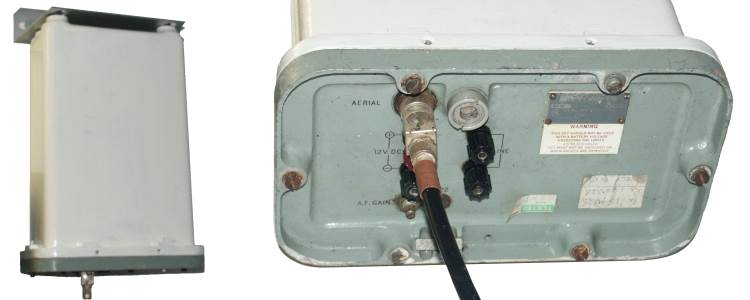
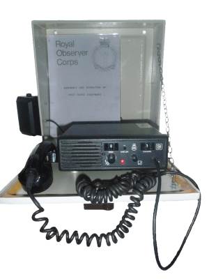
The post's radio is a Burndept BE525 Model M2010 to Home Office specifications, housed in a locked cabinet shown here. These are equipped with three channels, the first being its own Group's channel, the two other channels access adjacent groups, in case their own Group was destroyed by enemy action. Using only a single frequency simplex channel allows all master posts within range to make contact with each other. This opened up the prospect of relaying messages if direct contact by landline or radio was not possible.
I am very grateful to Mark P for kindly supplying detailed images of the radio front and back panels and two inside views. The first has the tone squelch (CTCSS) and 10 channel crystal oscillator boards in their normal position. The UKWMO only equipped three of the 10 channels. In the second view the boards are removed to reveal the main mother board of the radio.
Burndept BE525 ROC Post Radio$
A block of twelve frequencies are shared amongst twenty five UKWMO Groups. These twelve channels were in part of the Home Office allocation of 80.000 - 81.500 MHz also used by the UK Fire and Rescue authorities for mobile to base communications, before they moved to Airwave. The limited range of VHF radio signals allowed more than one Group to use a particular radio frequency without causing interference.
ROC Post RN4 Radio Channels
Group
Code
Frequency
Ch2
Ch3
Bedford
BED
80.2500
LIN
COV
Maidstone
MAI
80.2625
HOR
COL
Wrexham
NWA
80.2625
PRE
SHR
Oxford
OXF
80.2750
BED
BRI
Horsham
HOR
80.2875
WIN
OXF
York
YOR
80.2875
DUR
LIN
Bristol
BRI
80.3000
COV
SWA
Durham
DUR
80.3000
YOR
CAR
Preston
PRE
80.3125
CAR
NWA
Winchester
WIN
80.3125
BRI
OXF
Carlisle
CAR
80.3250
DUR
PRE
Carmarthen
SWA
80.3250
NWA
BRI
Lincoln
LIN
80.3375
BED
YOR
Yeovil
YEO
80.3375
BRI
EXE
Coventry
COV
80.3500
SHR
OXF
Exeter
EXE
80.3625
BRI
YEO
Norwich
NOR
80.3625
LIN
COL
Shrewsbury
SHR
80.3750
NWA
COV
Belfast
BEL
80.3875
PRE
CAR
Colchester
COL
80.3875
NOR
BED
This table shows the radio frequency used by each group in England, Wales and Northern Ireland. Posts belonging to the named group have the listed frequency as Channel 1 in their sets. Radio Channels 2 and 3 in Post radios were allocated to frequencies of two adjacent groups. All radios used FM modulation with Code Tone Control Squelch System (CTCSS). Tone 1 is used on all radios when working on the primary scheme, with tones 3 to 5 used for the secondary scheme.
Scottish Groups ROC Post Radio Channels
Group
Code
Frequency
Ch2
Ch3
Aberdeen
ABE
80.2500
DUN
INV
Ayr
AYR
???
Dundee
DUN
80.2750
Edinburgh
EDI
???
Inverness
INV
80.2875
In Scotland the provision of UKWMO and ECN communications was the function of the Scottish Office and little information appears to be available for the five groups under their control. ROC Documentation from England appears to suggest there were no cross border communications and omits the Scottish Groups from the interconnection diagram. The only Scottish radio that I have seen, confirms that inter-group communication was only possible within Scotland.
The table above was obtained from the designation plate on one post radio. Feedback via 'Contact Me' on the Home Page would be most welcome if you know the missing Ayr or Edinburgh Group radio frequencies.
Master Post Aerials
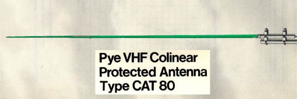
Pump Up Mast and 80 MHz aerial
The aerial chosen for the monitoring post radio is a dipole encased in a green glass reinforced resin tube. This is mounted on a guyed pump up mast. The inflation of the mast is performed from the safety of the monitoring room via a pipe running from the aerial connection box. This photograph of a print taken by Martin Cooke, Chief Observer at Stoke Golding, shows the mast and antenna during an exercise. The FSM dome and GZI can be clearly distinguished too.
Group HQ Equipment
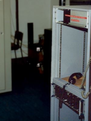
At Group Control, a radio rack houses the interface with the internal telephone system on the upper shelf and the Burndept BE458 radio transceiver on the lower shelf. The Post Supervisor at Group uses the internal telephone system and a special control box to speak to master posts.
Should the internal telephone systems fail, the Post Supervisor can move into the radio room and use the handset plugged into the lower shelf to communicate with the master posts.
RN4 Rack at Group
The first phase of the radio modernisation provided a BE458 base station operating on the 80MHz band at Group. This allowed communication with posts local to the Group HQ but in hilly or larger areas many distant posts were out of range. As all posts worked on the same frequency it was possible for messages to be relayed from the distant post via nearer ones. While this might have been acceptable for exercises it wasn't suitable for real action.
Phase two of the radio modernisation program rolled out hilltop sites connected via radio links to group much the same way as in the 1st Generation post radio. The links used Burndept BE458 working in the 168MHz and 174MHZ Home Office bands. The rollout of Phase 2 was protracted and not all groups were equipped before stand-down in 1992.
Up to three hilltop repeaters could be linked back to group using VHF highband radio links. Posts out of direct contact range of their group headquarters would select a CTCSS tone number for their nearest hilltop. All the hilltops used the same group frequency but with a different CTCSS tone for discrimination.
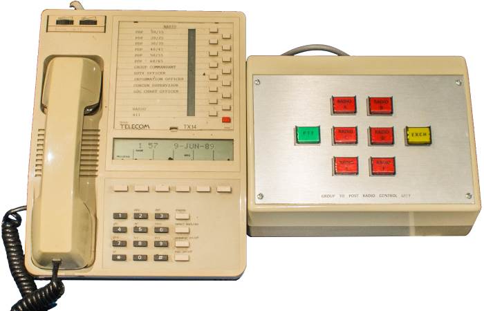
Post Radio to ECN Interface
The post radio interfaced with the Group HQ's PABX switch, part of the ECN Network. The post supervisor's TX14 Telephone has a button to connect it via the PABX to the radio system interface. After connecting to the radio, indicated by the yellow button glowing on the interface ( photographed at the Dundee museum ), the post supervisor uses the green push-to-talk button and other buttons to control the radio. Radio contact can only be initiated by the group. Should posts call while the group was off-line their call would go unheard.
Each 'Post Display Plotter' looks after two clusters of posts, if a landline fails, the post supervisor can set up a conference call with any plotter then operate the cluster by radio. It is necessary for the supervisor to stay on line to operate the push to talk button.
 This page is Copyright © RINGBELL.CO.UK, under a