This topic describes both the United Kingdom Warning and Monitoring Organisation (U.K.W.M.O.) and Regional Government Headquarters (R.G.H.Q.) communications from its inception in the early sixties, through the seventies and early eighties. Both networks collectively known as the Civil Defence network. A Home Office review identified the need for an upgrade which took place during the mid-eighties and replaced the systems described here by 2nd Generation equipment.
1st Generation Speech and Telegraph Networks
Overview of the Networks in the U.K.
The UKWMO network is used for its role in reporting of nuclear detonations and fallout warning. The Government Control Network (GCN) is used by Regional Government Headquarters (RGHQ), or Zone Headquarters (ZHQ) in Scotland to communicate with Local Authority Emergency Centres in their region or zone. Although the UKWMO and GCN networks are separate entities they were joined between the UKWMO Group and the RGHQ or ZHQ.
Both the UKWMO and GCN were of a similar design and interconnected so they can be treated as one, the Civil Defence Network. Both networks used GPO landlines to link between nodes. A single landline carried both speech and telegraph signals, at each node the speech circuit terminates on a telephone switchboard and the telegraph circuit in the message centre. Many of these links had a duplicate standby radio circuit provided by the Home Office, thereby making the link totally independent of the GPO network.
The UKWMO Private Network
UKWMO Network
Within the UKWMO there were two distinct networks. One linked Royal Observer Corp (ROC) Posts to their UKWMO Group Headquarters for speech only. The other larger network, shown in the diagram above, linked adjacent group headquarters together. This network had two sub-networks one for speech and the other telegraph. Telegraph is for sending hard copy messages between one or more places. At this stage of development, there was only a single landline with a standby VHF radio link between the adjacent groups carrying both speech and telegraph signals. The hilltop masts carrying these VHF links were often the same ones carrying the GCN at but as UHF links.
Although the UKWMO network only connected the adjacent group headquarters, the use of message centres made it possible to send messages between any two locations even though they were not directly connected. The messages could be broadcast to many locations if required.
Of the five UKWMO Sector Headquarters, only Preston and Lincoln Sectors were directly connected as they are adjacent, therefore all other inter-sector traffic had to be relayed via another UKWMO Group. During the late seventies inter-sector traffic had grown to an extent that warranted the installation of two direct landlines between each sector. Unlike the inter-group landlines, these newly provided circuits didn't have a radio standby.
Government Control Network
The Government Control Network (GCN) like the UKWMO network had two sub-networks, one for speech and the other for telegraph. The GCN was centred around the ZHQ or RGHQ, linking it with its adjacent ZHQ or RGHQ, Armed Forces headquarters (AFHQ) and each Local Authority Emergency Centre in the counties assigned to it. A single landline carried both speech and telegraph signals, with standby radio system links on important circuits. The bridge between the GCN and UKWMO networks was made between the UKWMO Groups and Regional or Zone headquarters serving the same geographical area.
I don't have a diagram to show the GCN network during the first generation time period. Instead here is an extract from a declassified document, the UKCICC(H) Joint Signal Instruction. At this time the document was written the Sub-Regional Headquarters (SRHQ) was the name for the RGHQ.
UKCICC Joint Signal Instruction Part 5
The Government Control Network
119. This network provides the following facilities:

     a. A landline and radio link between adjacent SRHQs, both within and
     outside individual regions.

     b. A landline and radio link from the SRHQ to each county wartime
     headquarters (both main and standby) within the sub region. In the case
     of Greater London, the SRHQ will be linked by line and radio to the
     headquarters of the 5 London groups and, in addition, each group will have
     a "speech only" radio link to an alternative SRHQ.

     c. A tape relay centre at each SRHQ, providing duplex (two-way) teleprinter
     facilities to adjacent SRHQs and to county wartime headquarters (both main
     and standby).

     d. A landline link from each SRHQ to the Emergency Manual Switching Scheme
     (EMSS).

     e. A landline and radio link from each SRHQ to a selected Group Headquarters
     of the United Kingdom Warning and Monitoring Organisation (UKWMO).

     f. A "speech only" radio link from each SRHQ to the headquarters of the
     various police forces within the sub region.

     g. A landline link between the main wartime headquarters of each county
     and an appropriate police headquarters.

     h. In the case of metropolitan counties, a landline and radio link
     between the main or standby headquarters of the county and the
     wartime headquarters of each metropolitan district.

     j. In the case of Greater London, a landline and radio link between the
     headquarters of each London group and the wartime headquarters of each
     London borough within the group.

     k. A "speech only" radio link between the headquarters of each London
     group and neighbouring London group.

     l. A landline link from each county wartime headquarters (both main and
     standby) and each London group to the EMSS.

120. Where both landline and radio links are provided, they are complementary,
and terminate on common switchboards. The landline circuits carry simultaneous
teleprinter working, with the radio link providing an alternative circuit if the
landline circuit fails.

121. UHF radios are also provided between SRHQs and the aircraft and helicopters
of the regional air squadron to facilitate the passing of reconnaissance reports.
If the squadron are reinforced by other light civil aircraft, other telecommuni-
cations might have to be improvised.

122. As a further standby measure, in each sub region there will be a reserve
of up to 10 HF radio sets. These are transportable, have easily erected aerials
and are omnidirectional. They have facilities to recharge their batteries or to
operate off standby generators. Their range is about 20-30 miles and consequently
they could be used in the last resort to plug the gaps in the GCN. They will be held
under Home Office control within sub regions.
Note. This document refers to a number of topics covered elsewhere on this website. These topics may be found in the website menu or in Alphabetic Index.
Para 120, The system for simultaneous speech and teleprinter working, is S+DX, there is a brief overview further down this page in the 'Telegraph and Speech over the same Landline' topic. A fuller explanation may be found in the Alphabetic Index / Speech plus Duplex
Para 121, refers to a radio known as AN/ARC 52 a topic within Post Attack Plans / RGHQ Tasks and Communications found in the website menu.
Para 122, is believed to be the SSB125 radio for the Last Ditch Network LDN. Details may be found under Post Attack Plans / LDN Communications in the website menu.
Para 119, sub-paras D & L, the Emergency Manual Switching System EMSS, has a whole topic devoted to it under Post Attack Plans / EMSS Communications in the website menu.
First Generation Telephony
From the sixties until the communications upgrade in the eighties the UKWMO Group, RGHQ and County Council bunkers had manual switchboards with a mixture of public telephone lines and private circuits for use by the extension telephones in the building.
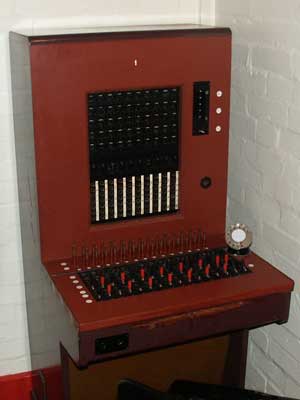
Private Manual Branch Exchange PMBX 10+50
The small Private Manual Branch Exchange (PMBX) shown here has the capacity of 10 exchange lines and 50 extensions, is of the type used at small control centres, such as those operated by County Councils. The PMBX10+50 was commonly used in the public network too. An extension would have to ask the switchboard operator to ring another extension. For outside calls the operator connected the extension to an exchange line and may have dialled the external number too.
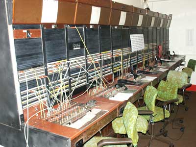
Larger Cord Type Manually Operated Switchboard
The larger multiple position switchboard were used in RGHQ and ZHQ bunkers on its own as a manually operated switchboard or in conjunction with an automatic switch. The automatic switches of this era were of the electromechanical type. The operator would connect incoming calls. Extensions could dial other extensions and usually dial an external number by prefixing it with a nine, but some establishments required the switchboard operator to connect an external call. Calls to other bunkers over the private networks of landlines and radio links, were usually connected by the operator.
An extension wishing to call another elsewhere in the private network would ask the switchboard operator to connect them. The operator would place the cord into the jack on the switchboard face and operate the 'ring' key. This would call the attention of the distant operator who would ring the distant extension. This could be quite a protracted process as each operator may be dealing with other calls. There may be only one or two lines between switchboards so extensions may have to queue to get connected.
War Emergency Network
During the nineteen sixties and the early seventies, long distance calls over 25 miles, were connected by the public telephone operator. In wartime that service would be compromised so the Post Office set up a small network of special switchboards in protected basement areas of telephone exchanges to maintain a long distance connection for emergency services. This network was known as the Emergency Manual Switchboard Service (EMSS). It was usual to provide direct landlines from the EMSS to ROC Group Controls, RGHQ and ZHQ as well as military sites, for use in an emergency should the public network fail.
Although automatic dialling of long distance calls became universal by the end of the seventies, the EMSS network was retained throughout the Cold War period as it was assumed the public network would suffer badly in an attack. Before the digitalisation of the UK network in the late eighties, the automatic long distance dialling network provided no alternative routing of calls if part of the network failed. Therefore it was important to retain a manual network which could adapt to a wartime situation.
The EMSS is described in its own topic if you wish to read more. Details may be found under the Post Strike Plans / EMSS Communications in this website's chapter menu.
Torn Tape Telegraph Message Centre
The torn tape message switching centre was extensively used in the Civil Defence network, at ROC Group HQ and Regional Government or Zone HQ prior to the communications upgrade in the mid eighties. Their use wasn't just confined to Civil Defence, but extensively used by the military, as well as large companies too.
Each bunker had its own message centre. They were connected to a small number of adjacent centres in their own network, to civil and military locations. A bridging link between networks were provided at ROC Group HQ and the RGHQ or ZHQ serving the same geographical area. Additionally there would be links to County Council bunkers
The telegraph circuit could send messages in either direction, and normally worked over a GPO/BT landline, but could be switched to an alternative radio link. Every circuit had a paper tape reader connected to the 'send' and a paper tape perforator connected to the 'receive' side. There were facilities to convert paper tape messages to printed copies for the bunker staff and to create paper tapes for outgoing messages from handwritten message forms.
Message Tape
The telegraph network used a 5-bit baudot code sent at 50 baud, which is very slow by today's standards but suited the mechanical devices it was designed for. The five hole code for each character was punched in a row across the width of a paper tape.
5 Hole Perforated Paper Tape
This type of paper tape was used by business Telex and for small scale use. The small piece of paper punched out of the hole known as a chad is undesirable in a message centre as they create disposal problems and tend to ingress into mechanisms causing faults. To overcome the problems a chad less tape was used which had a square hole cut on three sides but remains attached on the fourth side. To assist the relay centre operating personnel, the text of the message is printed down the side. The header sent before the actual message contains the sender and recipient information which can be read and interpreted by the operating staff.
Torn Tape Relay Centre
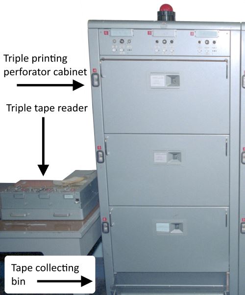
Printing Perforators
Each incoming circuit is connected to a dedicated printing perforator which perforates the tape and prints the character down the side, three being housed in each sound proof cabinet as shown below. Nevertheless this was a noisy working environment. The top section is open to show the mechanism and blank paper tape spool. There would be multiple cabinets in the relay centres. The punched tape emerges from one of three holes and collects in a bin below. When the message has finished the tape hangs from the front of the soundproof door ready to be torn off by the centre operators when the finished alarm was raised.
Printing Perforator Cabinet
At the top of the cabinet are three sets of supervisory lamps and control switches, one set for each tape perforator. As there is no message store in this system it was essential for the operator to ensure there was sufficient paper tape. A supervisory alarm is raised when the paper is low. The circuit has to be blocked to the distant end when the paper or print ribbon was changed.
Paper Tape Reader
Each outgoing circuit is connected to a paper tape reader, this creates a 50 baud data signal from the holes present in the tape. This is a purely mechanical device, having 5 tiny rods to sense the presence of a hole or not in the tape. Once one row is transmitted a sprocket wheel advances the tape to the next row.
Triple Tape Reader
Three reader heads are contained in one unit, matching the three incoming circuits in a cabinet. There are a rolls of tapes ready to be sent on top of the unit. Single headed readers were used in small communications centres that didn't act as relay points, such as those at a Local Authority Emergency Centre bunker.
Message Handling
This section describes in general terms the function of a torn tape message centre as used in Civil Defence in the United Kingdom.
Routing Rules
It is very important that message centres in a large network have a series of rules for handling messages. One obvious rule is if you don't have a direct link to the recipient, then specify which link to send it over, this is known as a routing table. Further rules are needed to cover the case when the desired link is faulty or destroyed by enemy action.
Special care has to be taken with messages intended to be broadcast to all recipients. Simply sending an incoming message to all outgoing links as well as printing it locally would not work. Messages would be duplicated many times and the sender would get their own message sent back. Without strict rules, a single broadcast message in a network would be like a snowball rolling down a hill and gaining size and crash the network.
Message Format
The Royal Observer Corp broadcast messages advising of bomb blasts or fallout reports circulated throughout the UKWMO and ZHQ Networks have their own special fixed formats to convey the information to the recipients.
Other ad-hoc messages between departments are prepared and transmitted in the protocol used by the UK Military and NATO, known as the 16 line message format. Although its not confined to only 16 lines, as the message line itself may take up a variable number of lines, but still counts as one line. Dependant on the message type some of the 16 lines in the format may be omitted.
Sending a Message
A paper message form is taken to the bunker's message centre where a typist transcribes the details on to a paper tape. In a tape relay centre this would be a special punch producing a paper tape and no paper hard copy. An example is shown below, as the typist presses the keys, the punched tape emerges from the left hand side of the unit. The message form contains the senders and recipient identity code that is needed for this centre and destination centre to be able to correctly route the message to the correct person or department.
Tape Punch and Document Holder
In small message centres, the tape could be produced on a teleprinter with a built in tape perforator such as the Teleprinter 7ERP which can be see in the Teleprinter topic further down this chapter.
The message starts with a header indicating the recipients of the message, the message itself and a run out of blank paper tape. This is torn from the perforator and carried to the tape reader on the link dictated by the routing rules. If the reader is already sending a message the tape is placed in a queuing system which might simply be a clip on the wall. When the tape has been sent, the centre operating staff check whether the message is a broadcast or has multiple recipients, in which case it is transferred to the appropriate reader and sent again to that destination.
Once a tape is placed in the reader, the start button is pressed to begin sending teleprinter signals to the distant end. If that is another message centre the associated incoming tape perforator reproduces a copy of the sent message tape. The distant end might be an end user with a teleprinter and not a message centre, in which case a printed copy of the message is produced. Typical end users of UKWMO messages are the Local Authority Emergency Centres.
Receiving a message
An alarm lamp illuminates to indicate the arrival of an incoming message. The centre operator tares the tape from the perforator and resets the alarm. If on visually inspecting the header it is for a local recipient the tape is transferred to a tape reader associated with one of the local teleprinters. The message is printed on the paper roll then torn from the machine and placed in the out-tray to be taken to the recipient.
Indirect and through messages
On receipt of an incoming message, the visual inspection of the header reveals the message is not for here but another recipient the tape must be retransmitted onward. The routing rules determine which outgoing link to another message centre is selected when the message is forwarded. It might be necessary to transit via a number of message centres to find the intended recipient.
Flexibility and Economy
A torn tape message centre was a very efficient way to achieve full message routing throughout a network of locations without having to connect every one to the others. It is very flexible too as the operators can use their intelligence to work around a fault or non functioning centre.
When the UKWMO telegraph network was introduced in 1968 it was piggy backed on the existing speech network using Speech plus Duplex technology ( S+DX ). A fully interconnected network connecting the 25 Group Headquarters in the UK would have required 300 links even though many links between remote points may never have carried a message. The actual network had 53 links, this economy of scale was possible as only adjacent headquarters were connected together, reducing the cost enormously, but it still enabled a message to be sent from any point to another via one or more tandem relay points.
Teleprinters for the 1st Generation Telegraph Network
A teleprinter of the cold war era was a large electro-mechanical device resembling an electric typewriter. There was a large public network of TELEX machines in the UK, which due to the high cost was almost exclusively for business use. The TELEX network was dial up, in a similar way to the telephone network, but the two networks were not connected. Some large companies had their own independent network which usually used Post Office leased private circuits. The Post Office Telegrams division had its own 'TASS' private network up until the seventies, for sending public telegrams. This used Creed 47 machines, designated as British Post Office No.11, these printed on a thin strip of gummed paper that was stuck to the telegram document.
Before the FAX machine became popular with businesses during the late eighties, teleprinters were favoured as an 'instant' communications medium as they produced a hard copy. The data rate which was considered fast at the time, was only 50 baud, with a 5-bit code plus 2.5 start and stop bits. The signalling was by sending 80 Volts Positive and Negative along the two wires. A good typist could type faster than the machine could send the characters, to prevent this happening the keyboard was mechanically locked stopping a second key from being pressed, until the previous character had been sent.
Teleprinter No. 7
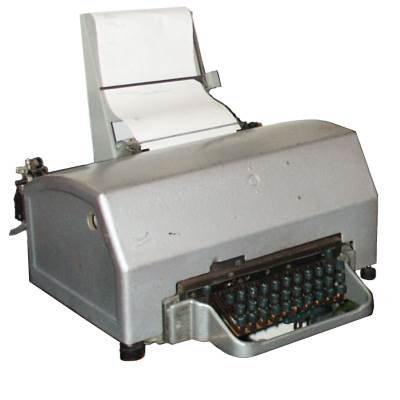
Creed 7B Teleprinter
The Creed 7B was used on both point to point links and terminal points on the home defence network. It has no paper tape facilities making it unsuitable for message centres. The mains power unit, a large box normally sited under the desk provides the 80 volts DC signalling. The motor has an integral speed governor. This makes the Creed 7 series teleprinter less reliant on good quality mains power and in a war situation suitable for use with a standby generator.
The No.7 designed in 1931 is ingenious consisting of hundreds of moving parts. This was the mechanical equivalent of the UART found in computer modems and decoded the 5-bit code and printed the character on the paper. Only capital letters, numbers and a limited number of special symbols were available.
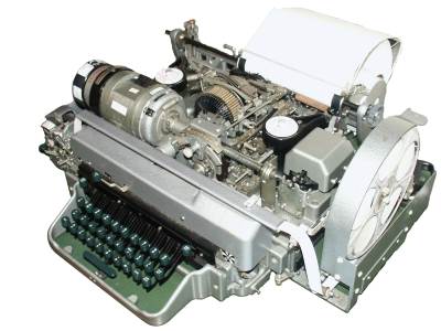
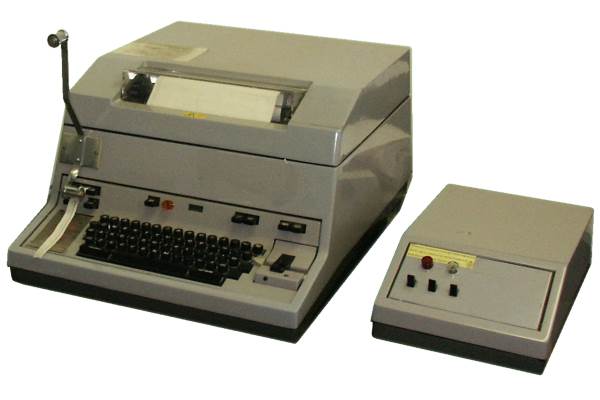
Creed 7ERP teleprinter
An improved version of the No.7 the 7E, used a different clutch arrangement, this overcame the problem where the 7B printed one character behind the one being received. In the photograph this version of the 7E is designated the 7ERP as it includes a tape re-perforator (RP). The electric drive motor and speed governor (the black a white round box) which powered both the printing mechanism and keyboard can be seen at the front left.
The 7ERP with a separate tape reader can be deployed in a small message centre with a few circuits. Like the 7B it isn't too reliant on a steady mains supply.
Teleprinter No.15
PO Teleprinter No.15 / Creed 444
The Creed 444 introduced in 1966 and designated the British Post Office No.15 replaced the old noisy No.7 printers for business use. The new machines had two colour printing, a built in paper tape perforator and reader. They were much easier to use as they had an improved keyboard and could store keystrokes. Later on, computer screen based devices were introduced, but the No.15 gave good service until the closure of the TELEX network.
Although the Teleprinter No.15 became well established in the TELEX network during the seventies I have little evidence it was adopted for the Civil Defence networks before the introduction of the electronic message switch (MSX). The reliance on a good mains supply to drive the synchronous motor made the No.15 unsuitable for use with standby generators. However it often appears in secret bunker museums, presumably because they were scrap items donated by BT, rather than being historically correct.
Telegraph and Speech over the same Landline / Radio Circuit
Economy Measures - Speech and Telegraph on one line
At this time, the rental of landlines was very expensive, so to avoid having two separate landlines for Speech and Telegraph a very clever system known as Speech plus Duplex Teleprinter, S+D or S+DX was used in the U.K. Civil Defence network to carry duplex teleprinter signals over the same wires as duplex verbal communication. This system was not exclusive to Civil Defence, but was used in the public network too.
This drawing shows the principle of the arrangement. At each end of the Private Circuit (Landline) a box of electronics combines the inter-switchboard speech line with a bothway link to a teleprinter or torn tape message centre. A more detailed explanation is given in the topic S+DX listed in the Chapter Index page of the website menu in the "Miscellaneous Topics" section.
In both networks, the S+DX could be switched to the radio circuit should the common landline fail. A special jack panel was provided to switch from landline to radio. During weekend ROC exercises, a test of switching to radio standby circuits was usually undertaken for about an hour.
Radio Backup to Landlines : First Generation
Within both the UKWMO and RGHQ networks radio systems were provided to act as a standby for the landline network.
The UKWMO network utilised single channel radio links in the VHF band. The more extensive RGHQ network radio links operated on UHF with both single channel per carrier and multiplexed links. The Civil Defence radio links used hilltop wireless stations, equipped with standby generators, already used for Police and Fire Brigade radio schemes. All these users are Home Office departments so it made sense using the same hilltop sites. The radio equipment was supplied and maintained by the Home Office Directorate of Telecommunications (D-o-T)
In the period from the sixties to mid-eighties the frequency bands were 147.000 - 147.300 MHz paired with 155.000 - 155.300 MHz which were a sub band of the larger 146 - 148 MHz and 154 - 156 MHz frequency assignment for Emergency Service use. An exclusive Civil Defence band 168.325 - 168.800 MHz paired with 174.025 - 174.500MHz was used exclusively for the UKWMO in accordance with notes N27 N29 in UK Table of Radio Frequency Allocations 1985, ISBN 0-11-513819-6
VHF Frequencies allocated for UKWMO Royal Observer Corp.
Shared VHF Band Channel Pairs
Civil Defence Exclusive Band Channel Pairs
147.000
155.000
168.325
174.025
168.625
174.325
147.025
155.025
168.350
174.050
168.650
174.350
147.050
155.050
168.375
174.075
168.675
174.375
147.075
155.075
168.400
174.100
168.700
174.400
147.100
155.100
168.425
174.125
168.725
174.425
147.125
155.125
168.450
174.150
168.750
174.450
147.150
155.150
168.475
174.175
168.775
174.475
147.175
155.175
168.500
174.200
168.800
174.500
147.200
155.200
168.525
174.225
147.225
155.225
168.550
174.250
147.250
155.250
168.575
174.275
147.275
155.275
168.600
174.300
147.950
155.300
UKWMO Radio Links
Inter UKWMO Group Radio Circuits
VHF radio links were provided to supplement the landlines. These provided a duplicate speech circuit between switchboards and additionally the telegraph S+DX could be switched over to use this reserve radio path should the landline fail.
The range of a single VHF radio link is limited to 30-40 miles, so a number of tandem links were required to connect the long distances between group controls. The Belfast to Preston link contains an exceptional hop across the Irish Sea from Slieve Croob to Cefn Du of approximately 118 miles, this only being possible with the use of a power amplifier and phased yagis, over an unobstructed sea path.
At the Group HQ bunker, a windup mast carries a number of VHF 3 or 6 element yagi aerials, pointing at the nearby Home Office D-o-T hilltop sites. Links on less physically obstructed routes might be mounted directly on the building's roof. The chain of hilltop sites use 6 element Yagi aerials on the links, a single aerial is used for both the transmitter and receiver. Some hilltop sites had more than one link between group headquarters passing through them.
The aerials are either mounted with their elements (rods) in a horizontal or vertical direction. Aerials at each end of the link will have the same element polarisation. An aerial of the opposite polarisation only receives a weak signal. This can be exploited to allow the same radio frequency to be reused in the order of fifty miles away if the element polarisation is different.
Coventry Group HQ Aerial Arrangement$
This arrangement at Coventry is typical of a group headquarter setup during this era. It has VHF radio standby links to seven other groups. The image gallery contains a larger version of this image marked with route, frequency and hilltop information and a route map. As well as the VHF yagis for the inter-group links and master post radio hilltop repeater link, there are two UHF yagis linking it to the two RGHQs in its area.
UKWMO VHF Link Details and Frequencies
The enlarged map shows all the individual radio links emanating from Wrexham, Shrewsbury, Coventry, Bedford, Lincoln and Norwich. And a partial set of information for the others. Where the routing of a radio circuit isn't known it is shown as a squiggly grey line. Appealing to ex-DTels staff - If you know the routing for any missing home defence radio links just a small part would be most helpful in building a bigger picture.
It has been suggested that not all the inter group radio links actually worked and some worked but had not been formally commissioned. All the VHF links were switched off as part of the W.A.R.C. project which changed the emergency service radio frequencies during the mid to late eighties. The old UKWMO VHF link frequencies in the 147 and 155 bands were reallocated to the emergency services when they migrated from 100 MHz, and the circuits migrated to the RN1 and RN2 networks that are described on the topic page for the 2nd generation of communications.
RGHQ Radio Links
In this first period the bands used were 452.000 - 452.225 MHz paired with 466.000 - 466.225 MHz and some additional channels in the larger 451 - 453 MHz and 465 - 467 MHz Emergency Services band which was mainly used for Police personal radios. There were two other bands 455.875 - 456.000 MHz and 468.875 - 470.000 MHz exclusively used for RGHQ links.
UHF Frequencies allocated for RGHQ UHF Network
Shared UHF Band Channel Pairs
Exclusive UHF Band Channel Pairs
Other Frequencies Channel Pairs
452.000
466.000
455.8875
469.8875
450.850
464.850
452.025
466.025
455.9125
469.9125
451.150
465.150
452.050
466.050
455.9375
469.9375
452.075
466.075
455.9625
469.9625
452.100
466.100
455.9875
469.9875
452.125
466.125
452.150
466.150
452.175
466.175
452.200
466.200
452.225
466.225
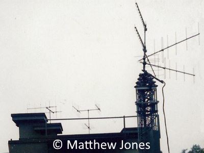
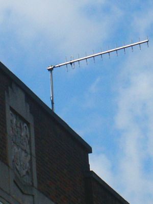
UHF 12 Element Yagi
The shorter wavelength of these UHF bands lends itself to the use of a high gain aerial with many elements. This photograph of a local council control centre shows a 12 element UHF yagi aerial, typical of the type used on RGHQ links to councils and other users.
Compared with a UKWMO Group HQ, there were a large number of circuits radiating out from a typical RGHQ, which dictated a different linking arrangement. If they operated a single channel per carrier like the UKWMO there would be problems due to the large number of individual transmitters, receivers and aerials required at the RGHQ as well as the hilltop sites. A technique known as multiplexing allows a single radio channel to carry seven circuits. One circuit is carried at normal speech frequencies and six are translated to higher frequencies, the resulting combined output is used to modulate the radio transmitter. The radio receiver output is fed into a demultiplexer to separate the individual speech circuits. A pair of multiplexer / demultiplexer equipment is needed at each end of the radio system.
Map of UHF radio links for RGHQ 4.2, Hertford
In this link map, the circuits from individual sites to the Thurfield mast are single channel links but the last hop to the RGHQ is a multiplexed link. A more detailed description of analogue Speech Multiplex process may be found on this website, via the A-Z Index 'Speech Multiplex' in website menu.


 This page is Copyright © RINGBELL.CO.UK, under a