Royal Observer Corp Monitoring Post Landline Communications
This topic records the development of ROC Posts landline communications systems. Mapping the gradual improvements from when the underground posts were built through to closure.
World War II Telephone for Cold War Use
After taking on the nuclear reporting role, underground posts were built around 1960-62 to house the observers well away from the hazards of blast and radiation. The original above ground posts were often left in situ and may be found at some posts today. Due to the shortage of telephone lines during the war period, a single landline connected a number of posts back to their control room.
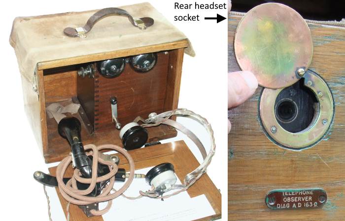
Telephone, Observer AD163
In use since WWII, the "Telephone, Observer AD 163", shown above, has a nice hardwood case. This is a magneto type telephone, called magneto as there is a generator handle which has to be rotated to call the distant end. A cord with its plug that locks into a covered socket in the rear of the telephone, connects with a headset and breastplate microphone worn by the observer. Some posts used the AD1542, an electrically identical telephone, with a cost reduced wooden case, dates from later in the war period.
In the early sixties this telephone was replaced with a loud speaking unit. The new device, known as a TeleTalk by the R.O.C., allowed the observer freedom to move around in the observation room and not be constrained by a cord.
1st Generation : Group HQ to Clusters of Posts by Landline
ROC Post Cluster Emergency Circuits
Posts were grouped together to form a cluster of generally three posts, but in practice the number could be from two to five. Each cluster was connected amongst its self with just a single landline back to Group. A typical cluster is shown above.
At either end of the group to post circuit, dedicated pairs of wires carried the circuit to the nearest telephone exchange. The remaining part of the circuit normally consisted of one or more switched lines. In peacetime these carried ordinary public telephone calls between telephone exchanges. For Royal Observer Corp exercises, or in time of war, these emergency circuits were switched over for ROC use. These were known as an 'Emergency Circuit' as they were to be used in an emergency only. On a post's drill night they were not switched, so there was no way to communicate between Group HQ and Posts.
The circuits were designated with the letters 'EC' meaning 'Emergency Circuit' and five digits e.g. 'EC20221'. The Range 20000-29999 being allocated to the ROC. Switchboard operators employed by the GPO / Post Office Telephones / British Telecom up until the mid-eighties may recall being involved with the switching of the ECs as they were commonly known.
Switching the Emergency Circuits was a complex task when considering that in 1964 Oxford Group alone had 46 posts in 12 clusters and required switching a total of 109 switching points at 51 different telephone exchanges. This was replicated up and down the country some twenty-five times. At each staffed exchange, the switching was done manually, by either a switchboard operator or engineer. At unmanned remote exchanges, the switching clerk in the main exchange had to initiate three calls to two different telephone numbers in a set sequence and time interval.
At manual switching points, firstly a 'Busy' key stopped the line being used for telephone calls, if a call was in progress on the line to be switched, a small lamp flashed until it completed. When the lamp glowed steadily, coloured pegs were moved from the 'normal' to the 'switched' position. This was fraught with problems as it was very easy to misoperate the switching for each ROC exercise
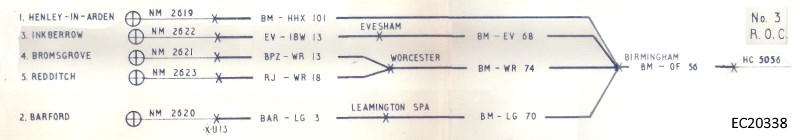
Example : Oxford 1964 One Cluster's Emergency Circuits
In the example above, Henley-in-Arden post has a private circuit NM2619 to its local exchange where it is switched onto the Birmingham (BM) - Henley (HHX) circuit No. 101, at the Birmingham end it is switched into the the teeing point. Inkberrow has a private circuit NM2622 to its local exchange where it is switched onto the Evesham (EV) - Inkberrow (IBW) circuit No. 13, this circuit is switched at Evesham to the Birmingham - Evesham circuit No. 68, at the Birmingham end it is switched into the teeing point. Likewise for Barford but its intermediate switching point is Leamington Spa (LG). The circuits from Bromsgrove and Redditch are teed at Worcester onto a single circuit to Birmingham.
At Birmingham the four switched circuits from Henley in Arden, Evesham, Worcester and Leamington are all teed together and switched to the Birmingham (BM) - Oxford (OF) circuit No.56: At Oxford, the Birmingham No.56 circuit is switched to HC5056 a private circuit to Oxford ROC Group building. Switching of only this one Emergency Circuit EC20338 has taken 9 lines out of service that are usually used for normal telephone calls.
First Generation TeleTalk
In use since WWII, the "Telephone, Observer AD 163", shown above, is a magneto type telephone, as there is a generator handle which has to be rotated to call the distant end. The generator is called a magneto. A cord with its plug that locks into a covered socket in the rear of the telephone, connects with a headset and breastplate microphone worn by the observer. In the early sixties this was replaced with a loud speaking unit. The new device, known as a TeleTalk by the R.O.C., allowed the observer freedom to move around in the observation room and not be constrained by a cord.
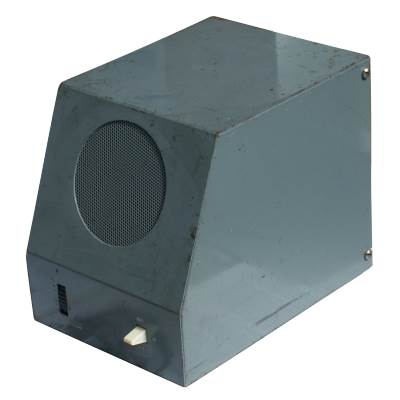
1st Generation Teletalk: Unit Intercom LB AD3460
The TeleTalk or "Units Intercom LB AD 3460" to give its proper description is battery powered, hence LB in its description for Local Battery, utilising the same design of 6 volt dry battery [Battery, Dry No. 27] fitted in the Warning Receiver. Additionally a 67.5 volt battery [Battery, Dry No. 18] is used to send the call signal to the post display plotter. AD3460 is the diagram number, the letters AD designate a series of G.P.O. diagrams for Air Defence equipment.
There are photographs both batteries in the gallery. Note, the Battery Dry No. 18 is marked as a radio battery, as in days before transistor radios, this type of battery would provide the high tension for thermionic valves in a portable radio.
Normally in receive mode any conversation on the cluster's omnibus line may be heard. Before speaking into the loudspeaker which acts as the microphone too, a small lever switch on the right hand side of the unit must be pressed downwards. Posts within a cluster can communicate amongst themselves by voice calling. But to attract the attention of the plotter in Group HQ, the lever switch is momentarily pushed upwards to the CALL position and then released.
As posts were usually located on remote hilltops the pair of wires feeding them were often carried on poles along field boundaries making them very vulnerable to blast damage. The same wires fed both the Warning Receiver and the TeleTalk, so both would be out of action if the line was broken.
Telephone engineers regarded these overhead lines as a bit of a joke. In the film Hole in the Ground, the featured post sent an observer out in the fallout to clear the line faults caused by the bomb exploding. This was not an easy task in peacetime yet alone a post nuclear holocaust.
$
2nd Generation : Group HQ to Clusters of Posts by Landline
Starting in 1981, the landlines to Group Headquarters were converted from switched Emergency Circuits to permanently connected Private Circuits (Private Wires 'PW'). The previous arrangement of switching the lines meant this could only happen for main exercises. Therefore the TeleTalk couldn't be used on a normal drill night. The change to permanent circuits made it possible to communicate with the other posts in the cluster and Group HQ at any time.
Cluster Private Wires
The new Private Circuit to Group HQ operated over four wires. This led to an improved quality of communications around the cluster and back to Group. During modernisation of the landlines many of the very vulnerable overhead wires were replaced with an underground cable. The new circuit from the telephone exchange to the post operated over four wires, one pair of wires conveying both the speech towards the TeleTalk also the carrier and trickle charge for the post's early warning receiver. The other pair conveyed the speech away from the TeleTalk and supplied its power from the telephone exchange's power supply, no batteries were required in this design.
This table below shows the BT Omnibus circuits feeding each of the ten clusters of posts in the Shrewsbury group. The private circuits (private wires) number PW20260 to PW20269.
Cluster Private Wires
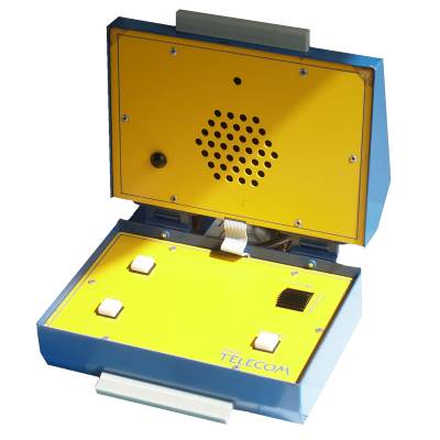
Second Generation TeleTalk
The original Grey TeleTalk was replaced with the more colourful modern AD8010. This derived its electrical power from the public telephone exchange 50 volt battery via the private wire thus removing the need for a stock of batteries at the post. Larger telephone exchanges had standby generators should the electricity supply fail, which is very likely during a war situation, by the eighties many smaller exchanges had standby generators too, keeping the exchange batteries fully charged.
This new design of TeleTalk still retained the simple controls of the earlier model. The 'CALL' button calls the attention of the plotter at Group HQ. The device is normally in receive mode and monitors any conversations taking place within the cluster of posts.
The 'TRANSMIT' button must be depressed to switch to talk mode. This is very much like operating a radio transceiver or intercom. The loudspeaker and microphone are in the hinged lid that is normally kept closed to press the 'ON' button down to switch it off. When in use, the lid can be angled to suit the user, who speaks about 9-12 inches away from the microphone.
 This page is Copyright © RINGBELL.CO.UK, under a