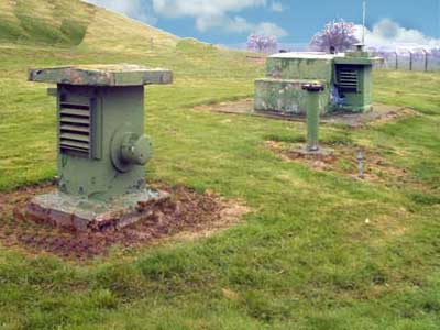
This photograph is typical of the exterior view of a ROC observer post. A 20 ft vertical ladder leads to an underground chamber only 7ft x 16ft x 7ft high. This houses the observers and their instruments and welfare facilities. Conditions were very primitive, as there was no running water, gas or mains electric.
Typical ROC Monitoring Post
A full description of the post and its instruments are given further down this page after the location maps.
ROC Monitoring Post Locations
The ROC Posts within each Group Control area are arranged in clusters usually containing three posts, but can be from two to five. One post is designated as the master post. Master posts are numbered from ten with an interval of five (10, 15, 20 etc.) usually starting in the North of the area and working down left to right. The significance of the clusters is explained in accompanying communications sections in the website menu.
Individual posts within the cluster are numbered sequentially in a clockwise direction starting from the master post (10, 11 & 12)(15, 16, 17 & 18.) and are unique only within that group and marked with a red spot. The other posts are marked in blue and green lines join all the posts within a cluster.
Key Points to Note on Maps
You may view the maps by using the selection buttons, to print a map for non-commercia purposes, please use the link at the bottom of this page or the website menu to navigate to the Mapping Library.
These maps represent the situation in March 1989 and do not show the monitoring posts closed as a result of the 1968 spending cuts. If you are interested, photographs of every extant post may be found on the Sub-Brit website (http://www.subbrit.org.uk/).
Physical Appearance of a ROC Post
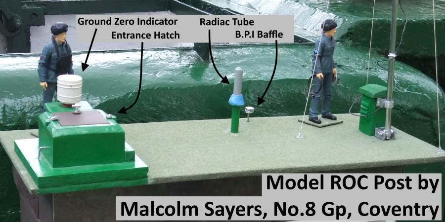
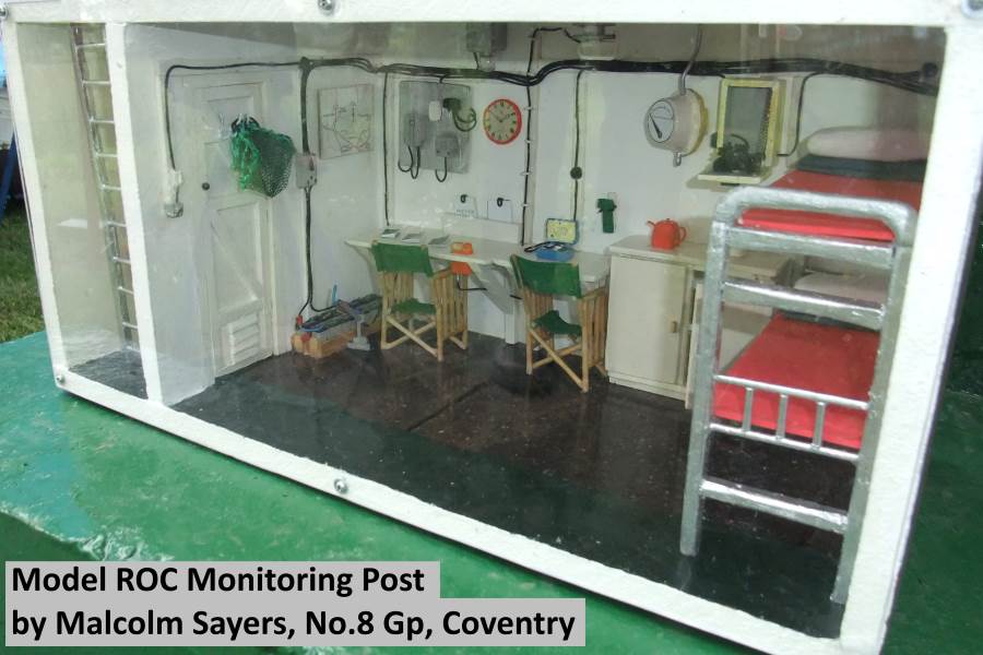
All these years since the ROC stand down makes it difficult to find clear photographs of the surface features of a nuclear monitoring post in a state of readiness. Malcolm Sayers has kindly allowed me to use these photographs of his model to illustrate the salient points of a typical R.O.C. Post as it would have been at stand down in 1991.
Surface Features of a ROC Nuclear Monitoring Post
This is a typical view of the exterior of a ROC monitoring post ready for action. A locked entrance hatch leads to a 20 ft vertical ladder down to an underground chamber 7ft x 16ft x 7ft high. The main room houses the observers, their instruments and welfare facilities. A chemical toilet is located in a small room at the bottom of the ladder. Conditions were very primitive, there was no running water, gas or mains electric.
The only communications with the outside world is the loud speaker intercom device, connected to UKWMO Group HQ and the other posts within the cluster. There was no other means of two way communication as there wasn't a telephone provided. The post had a Warning Receiver to receive instructions when to sound the hand operated siren or maroon. The designated master post in each cluster had a radio for a backup to the landline intercom device.
When not in a state of readiness the radiac tube cover and Bomb Power Indicator (BPI) baffle were removed and replaced by blanking plates. The Ground Zero Indicator (GZI) camera was unbolted and stored inside the post. The pump-up aerial mast was deflated and stored in the ladder shaft.
Originally the only air supply was via two louvered vents, one on each end of the chamber, which meant it could be quite damp. Latterly some posts were fitted with power operated fans. Some posts leaked ground water which had to be pumped out before it could be manned. One has to admire the dedication of people prepared to lock themselves away in these cold and damp conditions for 2 to 3 weeks if there had been a nuclear attack on the U.K.
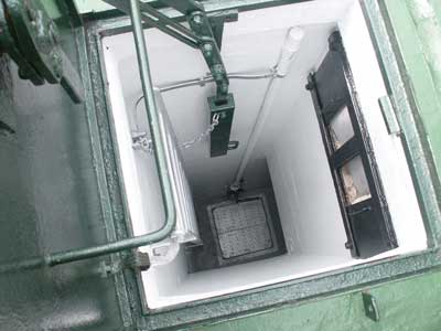
Looking Down the Hatch
Looking down the hatch into the post from the step, we can see the hatch counter weight. At the top left is the ventilation grill and control plate. The grating at the bottom of the ladder covers the water sump. Next to this is a hand operated pump and a vertical pipe to expel the water. The toilet door is on the right and the observation room door at the bottom of the photograph.
Nuclear Monitoring Room
The model shows the layout of a typical observation room at a master post in an unbelievable level of detail. It is very sparse and functional with just a handful of instruments and communication devices. A 6" striplight or a bulb provide the only lighting. We can see the radiac survey meter (Geiger Counter) and bomb pressure indicator. These instruments are described in detail further down this page. The communications equipment comprise of a Teletalk intercom, warning receiver and as this is a master post, a radio within its wall box. These communication devices are briefly described further down this page and in more detail on a separate page, ROC Post Communications, accessed from the website menu.
Instrumentation
Monitoring Nuclear Weapon Detonations
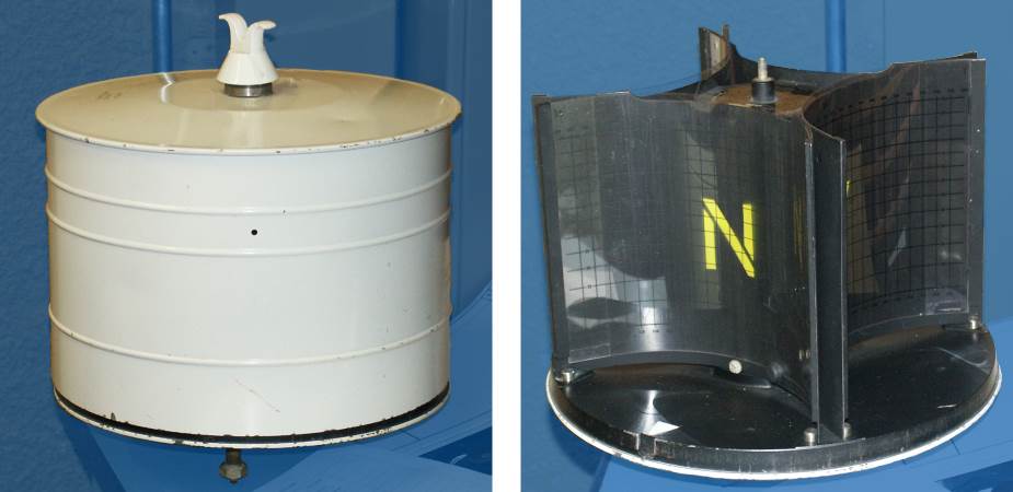
A Ground Zero Indicator (GZI) was employed to record the position of a nuclear detonation. This consisted of 4 pinhole cameras in one enclosure. One of the pinholes can be seen in this photograph. The camera is bolted onto a bracket on the outside of the post on the entrance hatch.
Ground Zero Indicator External and Internal Views
Facing each pinhole is a cassette containing photographic paper. This is marked with a matrix of lines giving the bearing and elevation. Light from the fireball passes through the pinhole and marks its position on the photographic paper. Following a detonation the observer exchanges the cassettes and returns to the monitoring room to examine the markings.
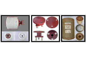
Detailed Photos of GZI$
Paul Lawrence has kindly shared the photos in the gallery showing close-up details of the GZI instrument. This unit has never been installed and comes complete with its mounting bracket which is cemented into the front ventilation turret.
The instrument label reads INDICATORS, GROUND ZERO, RADIAC EQUIPMENT / Joint Services Cat. No. 6665-99-911-0403 The instrument base moulding has a different catalogue number ending -0404, the mounting bracket -0405 and the cover -0406, so they can be ordered separately if replacements parts are needed.
Points to note: Offset hole in mounting to ensure correct orientation of instrument to the points of the compass. Peg to prevent the wrong cassette being placed in the camera face. Internal lug on cover to align the pinholes in front of each cassette. Slot in base marked with arrow, to accept lug on cover. External paint mark indicating position of lug. The delivery carton in discarded and the GZI Instrument is stored inside the post in a white plastic container (not shown).
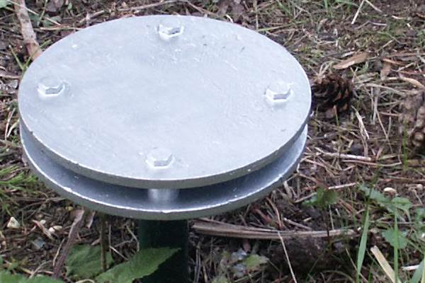
Bomb Power Indicator Pressure Wave Baffle
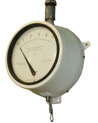
To detect and measure the size of the shock wave from a nuclear detonation, a baffle plate above ground collects the pressure wave and feeds it into a pipe down into the post below. When the post was not manned the baffle is replaced by a sealing plug. At the other end of the pipe is a wall mounted pressure detector known as a Bomb Power Indicator (BPI). It's needle displays the highest peak pressure of the blast wave and remains there until reset by the observer.
Wall Mounted Bomb Power Indicator
Immediately a pressure wave is recorded, the observer waits 10 seconds to ensure this is the maximum reading and resets the instrument. A call is made to the Post Display Plotter (PDP) in Group HQ using the Tele-Talk unit or Radio. The spoken message in the format TOCSIN, followed by the Group name, Post Number and time. The PDP responds and the post gives the pressure reading in kilo-pascals.
Post speaks:
TOCSIN HORSHAM TEN POST - TEN OH ONE - OVER
Plotter Calls:
TOCSIN HORSHAM TEN POST - TEN OH ONE - OVER
Post Speaks:
PRESSURE ONE ZERO - OVER
Plotter replies:
THANK YOU - OUT
When one minute has elapsed from the last BPI reading of 2.0 kPa or more, the number three observer goes outside to replace the GZI cassettes holding the sensitised paper and bring the exposed ones down for examination.
For each of the spots recorded by the GZI the readings are passed to the PDP. The format being, time of retrieving the cassette, bearing direction, elevation and spot size in degrees of the fireball and if it is touching or clear of the ground;
Post speaks:
NUCLEAR BURST HORSHAM TEN POST - OVER
Plotter replies:
HORSHAM TEN POST - OVER
Post speaks:
TEN OH FIVE - BEARING TWO ZERO SIX - ELEVATION ZERO FIVE - TOUCHING - SPOT SIZE ONE ZERO - OVER
Plotter replies:
THANK YOU - OUT
Group HQ staff use triangulation to determine the exact point of detonation once they have bearing directions from two or more posts. Having determined the position of the detonation, Group HQ can estimate the yield (size) of bomb from the pressure wave readings received from the posts. Knowing the distance from each reporting post to the detonation, the height of the centre of the fireball can be determined from the elevation readings taken by the GZI. Elevation is important as a detonation at ground level (ground burst) will create fallout. Whereas a similar bomb exploding so its fireball did not touch the ground (air burst) would create little fallout. It was assumed the enemy would use a combination of air and ground burst weapons.
Monitoring Fallout Radiation
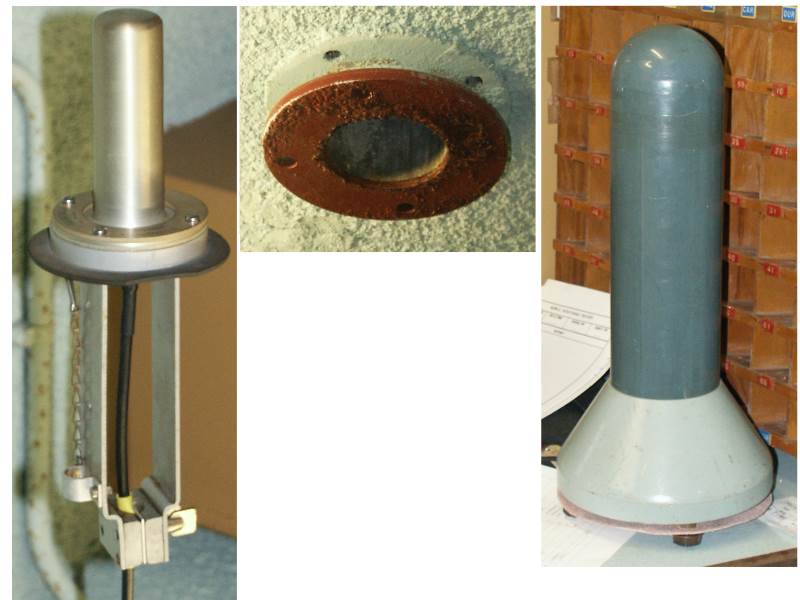
From the safety of the underground room, the observers can monitor fallout radiation levels, using a Fixed Survey Meter (FSM). A type of Geiger counter. Its probe head is mounted on a rod, which is pushed up a pipe extending from a flange in the ceiling, up into a protective grey tube on the surface. The various parts may be seen in the photo below.
Fixed Survey Meter Detector Head, Ceiling Flange and Protective Dome
If the radiation level approached the maximum range of the instrument, the FSM head would be withdrawn down the tube and refixed at a point where it indicates a tenth of the fully extended level. This would be repeated if the radiation approached the maximum range again, so now the indicated reading would be one hundredth of the surface reading.
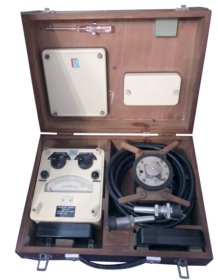
Alistair McCann has kindly provided the next two photographs of the original design of fixed survey radiation meter and the training unit used during exercises.
Original Fixed Survey Meter in Box
The box contains the FSM and 'Mallory' batteries, providing 10.5 volts for the device. The survey head is housed on the right hand side of the box. The thick black connecting cable is wrapped around the head's container and held in place with four wooden clips. Each end of the cable has a special screw on connector to mate with the detector head and FSM instrument.
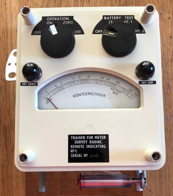
FSM Training Simulator
A special training unit was used during exercises to simulate the arrival and subsequent decay of the fallout. Pre-prepared acetate strips were rolled onto the spindle at the bottom of the photo. This strip was fed into the unit by a clockwork mechanism, its winding key protrudes from the left hand side of the unit. The width of the strip varies along its length, causing the meter reading to rise and fall in sympathy.
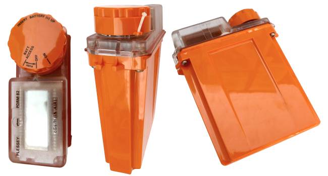
During the eighties, this older design of thermionic valve operated Geiger counter was replaced by an electronic unit, with a digital display. The new design of FSM device fits into a slot in the monitoring room desk so that it can be read easily. The cable linking it to the probe head exits from under the desk keeping things tidy.
Fixed Survey Meter PDRM 82F$
After the Attack Warning Red has been received, the observers begin making regular readings of the radiation levels. If the radiation level rises indicating fallout, the post initiates a 'First Fallout' call to the Post Display Plotter. If a Fallout Warning Black is issued via the carrier receiver, or independently of that, the FSM reading rises to 0.3, the post will set off the fallout maroons to warn the local population. This procedure ensures a fallout warning will be given even if the carrier receiver has stopped working.
Post speaks:
FIRST FALLOUT HORSHAM TEN POST - OVER
Plotter replies:
HORSHAM TEN POST - OVER
Post speaks:
THIRTEEN THIRTY TWO - OVER
Plotter replies:
THANK YOU - OUT
The 'First Fallout' message initiates the start of a time cycle. Once the time cycle has started the PDP will call every post in the cluster on a five minutes cycle, asking for a fallout reading, enabling Group HQ to plot the progress and path of the fallout plume.
Local Weather Reports
Selected posts known as ROCMET posts, had rudimentary equipment to allow them to make simple meteorological reports. These are passed to Group HQ for relaying on to Sector Headquarters. If the United Kingdom Meteorological Office (Met Office) was knocked out and couldn't produce weather forecasts, UKWMO Sectors could generate their own forecasts to enable the path of fallout to be calculated.
ROC Post Communications Overview
The primary means of communications was the Loud Speaking device known as a 'TeleTalk' connected to a landline private circuit to the Group Headquarters. The same private circuit also brought the carrier signal from the exchange to the Warning Broadcast Receiver, a listen only device. The post designated as 'Master Post' in each cluster also had a VHF radio as an alternative way to contact Group Headquarters if the landline failed.
In 1981 a Home Defence Review had recognised the need to improve and update the communications and equipment in use in the ROC. During the life of the posts there were two distinct equipment eras, these alternative devices are shown below, and full descriptions given in the Post Communications page or the WB400 / WB1400 pages, found in the website menu.
Contrary to some belief there wasn't a telephone in the post. Neither did it have a way to speak to the local police station. This later myth may be as a result of the police being the source of the warning broadcasts.
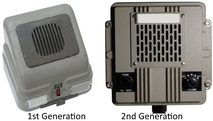
TeleTalk Device is the Primary Means of Communication
When switched on, the TeleTalk would be in listen mode on the private circuit. If the 'Post Display Plotter' (PDP) in Group HQ spoke the message would be heard at all the posts in the cluster. To speak back, a switch was depressed, and the observer spoke towards the loud speaker grill, the other posts in the cluster would hear the reply to Group. To initiate a message to Group, the observer would press the 'CALL' button to attract the PDP's attention. As the arrangement is very similar to an intercom, the posts within one cluster could talk amongst themselves without involving Group.
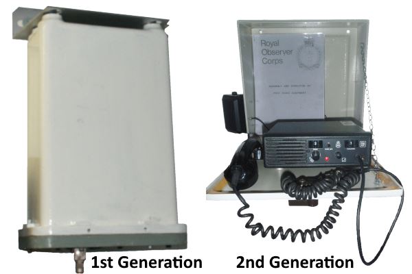
Radio Backup at the Master Post
If the TeleTalk landline link back to Group was severed, but the local landlines to the other posts in the cluster were still working, the master post would collect the readings and messages from the cluster's posts, then radio them through to the PDP in Group HQ. Not all Groups had first generation radios, Belfast No.31 didn't have their radios until the second generation came along.
Carrier Receivers
In common with all warning points, the ROC Nuclear Monitoring Post had a carrier receiver allowing them to receive the National Attack Warning Red, Fallout Warning and All Clear, allowing them to warn the local population.
Public Warning Functions
ROC Posts have both a observing and monitoring role and to act as warning points for the local population. If there is not a ROC post near a village, this role as warning point may be carried out by the local police or a trusted individual such as postmaster or pub landlord. In common with other warning points, the post has a hand operated siren. This siren is normally kept packed in a crate, but when the post is manned for a war situation, it will be unpacked and placed outside the post in readiness.
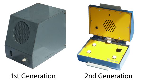
Hand Operated Siren
Fallout warning is given to the public by means of a pyrotechnic maroon. The maroon is a large firework that shoots three shells high into the air which explode in a bang-bang-bang sequence. Due to the danger of handling live maroons containing explosives a training kit was provided for use during exercises. It was intended that live maroons would be only issued during the transition to war.
Fallout Warning Maroon
The 2nd Generation training kit is shown in the second image in the gallery. The third image in the gallery shows the yellow training maroon connected to the firing controller. The trainer has three bulbs to indicate the firing of each tube. As live maroons would not be issued until the last moment, to enable personnel to familiarise themselves with a real device, the kit also contains a dummy maroon made to look as closely as possible to the real thing, coming inside the same packaging material as a live device. The dummy maroon alongside a live device are shown in the fourth gallery image, the only visible difference is the word "dummy" printed on one leg. The kit also includes the same instruction card as the live maroon, a copy is reproduced in the gallery. I am most grateful to Alistair McCann for gallery images of the 1st Generation maroon and the 2nd Generation trainer / deactivated live device photos. Also a photo of seven spent rockets from inside the 2nd generation maroon. The black tape held the explosive charge in place.
The same controller box is used for both the live and training maroon. The maroon controller connects via a six-way plug and long black wire, so the user would be at a safe distance when this powerful firework ignites. The controller contains a dry battery, but an adapter (with the red wiring) allows it to be operated from a car battery or the post lighting / radio battery.
 This page is Copyright © RINGBELL.CO.UK, under a