A brief summary of Wire Broadcast ( WB ) systems employed by the Post Office Telecommunications / British Telecom in the period before 1990 but not used for Civil Defence purposes. All the colour photographs on this page were taken at Avoncroft Museum, Bromsgrove, in their Telecoms display area.
Those WB Numbers allocated to Civil Defence are shown grey for completeness and are described in the "National Warning Scheme" section of this website, use the top Navigation Menu Bar or the quick links at the bottom of this page.
WB200 Early Trial of Warning Speech Broadcast System - See HANDEL
Carrier System WB300 - Nuclear Radiation Leak Warning System
This topic is a place holder as I have little specific details of this system, other than it operated over the on-site PABX network at the Atomic Weapons Research Establishment (AWRE) Aldermaston. I welcome any further information and feedback via the website Home Page.
Receiver Carrier WB303A
The G.P.O. Engineer-in-Chief Reports for 1954 - 1965 held in the BT Archives reveal quite a lot about the development of a system for the U.K. Atomic Weapons Research Establishment (A.W.R.E.) The 1955-56 Report, says a system with 3 control points and 500 Receivers (using valve technology) had been supplied and partly installed. By 1957, a further 100 transistorised receivers were needed, but a shortage of transistors delayed the supply until 1958-59. By the 1959-60 report the number of working receivers was 600. The 1963-64 Report says The warning system operated by carrier working on the P.A.B.X. network at this establishment [ A.W.R.E. sic] continued to grow and additional equipment was provided to give automatic alarm facilities in selected areas in case of a criticality incident.
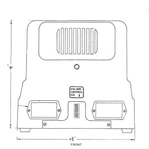
The final mention of the A.W.R.E. comes in the 1964-65 Report, Contracts were placed for transistor-type receivers to replace the original valve-type receivers which have been in continuous use since 1955 and are now approaching the end of their useful life. The new receivers should have a much longer life and low fault liability; the use of transistors enables stand-by batteries to be provided using nickel-cadmium cells. These receivers, A Receiver Carrier WB303A, have a very similar appearance to the Civil Defence WB400 receiver, with the addition of a red pilot lamp on the front under the speaker and a plate covering the area occupied by the drawer.
WB400 Public Early Warning Speech Broadcast System - See HANDEL
Electricity Load Control - was it WB500 ?
The G.P.O. Engineer-in-Chief Report for 1960/61 quoted The Central Electricity Generating Board asked the Post Office to consider the possibilities of providing means by which Area Electricity Boards could modify unpredictable load peaks by shedding and restoring loads of the thermal-storage space-heating type, by remote control over Post Office lines. Control would be required over several telephone exchange areas from each control point, with selective control to enable the loads of consumers accorded high priority to be disturbed as little as possible. The requirement has been discussed in the Engineering Department and proposals have been made to the Administration as a basis for negotiation with the Central Electricity Generating Board. It is proposed that the Post Office should provide carrier wire broadcast transmission networks operating at 20 kc/s over working audio junctions and subscribers' lines, the Electricity Boards to provide and maintain, in an approved manner, equipment for sending and receiving coded pulses of carrier at pulse rates of about 10 c/s and below.
Amplifying equipment for six exchanges was produced and installed. One hundred receiving equipments and one sending equipment of approved design were ordered from a contractor by the Central Electricity Generating Board. The progress was reported in 1964-65 as The field trial of control equipment in the Greater London Area has been completed. Tentative proposals have been made for an operational trial in a Midland Area.
This system may have been designated as WB500, as this range is missing from those I know about. Later on the control of load shedding took place using the Radio Teleswitch Service sent as a carrier on BBC Long Wave transmitters. After the closure of WB1400, some local authorities used Teleswitch for their flood warning sirens.
WB600 Public Early Warning Siren System - See HANDEL
Signalling System WB700 - Propagation of Local Call Timing in the GPO Network
The WB700 had nothing to do with Civil Defence itself but carried call charging information to small exchanges. In mainland U.K and Northern Ireland, it utilised the Civil Defence WB400, 72kHz carrier for this purpose, which avoided the expense of a separate network of lines conveying the charging information. The Isle of Man did not have WB400, so a Carrier System WB700 was installed to provide the 72kHz carrier, instead of using the one generated at Police CCP's.
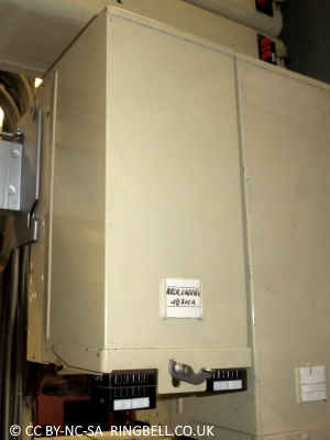
WB700 with dust cover in place
Prior to the introduction of Subscriber Trunk Dialling (STD) telephone customers could only dial local calls themselves. Calls to places further a field were connected via the operator, who timed and charged the call. Local calls were charged between one and four metered units depending on radial distance irrespective of the call duration.
The introduction of STD in the UK during the early nineteen sixties brought a new call charging regime. Local calls were charged by duration only. STD calls were charged by both radial distance and duration. The radial charging rings for STD were designated 'A' (less than 56 Km), 'B' (more than 56 Km) and 'C' (Channel Islands).
Call charge rates were also affected by the time of day, day of the week and type of customer. Coinbox customers or public telephone kiosks paid a higher rate than ordinary residential or business customers.
To enable small exchanges to charge for local calls by duration, it was decided to generate the timing signals in the main exchange and distribute this out to smaller units, thereby avoiding the expense of sophisticated timing equipment in every small exchange. The Signalling System WB700 was devised as a means to distribute local call timing signals for Ordinary (ORD) and Coin Collection Box (CCB) customers.
Wire Broadcast System WB700 Schematic Diagram
At the main exchange, accurate call charge timing signals were created by the multi phase pulse supply. Those for local calls were fed to the WB700 oscillator and modulator contained within the Control Point Exchange ( CPE ) equipment cabinet. Timing signal pulses generated a sub audible signal of 44Hz for ORD customers and 26Hz for CCB customers. The sub audio signals modulate the 72kHz carrier as it passes through the CPE cabinet from the WB400 Carrier Control Point to the distribution network.
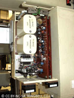
Receiver WB700 Internal View
At the dependent exchanges a Receiver Carrier WB700 is fed from the WB400 distribution cabinet. The carrier is demodulated and the two sub audio tones filtered from the ticks and audio of the WB400. Each tone is amplified to operate the appropriate meter pulse 'M' relay, MO for Ordinary, MC for Coinbox. These relays extend the timing signal to the local call timing devices in the telephone exchange switch block.
Replacement for WB700
In the early Eighties the planned replacement of the WB400 caused a rethink in the generation of local call timing pulses. The fall in cost of electronic circuitry and the invention of the integrated circuit made a new solution possible.
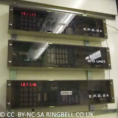
Equipment Pulse Generator 2A
A custom designed quartz clock known as an Equipment Pulse Generator 2A was installed in small exchanges to provide the local call timing information. Each installation consists of two pulse generator units and a changeover unit to ensure the resilience of the call charging. These were used until 1995 when the last step by step analogue exchanges were replaced with a modern digital network.
The digital network had to be fully in place for PhoneDay on 15th April 1995, when the UK area codes 0XXX became 01XXX and all the mobile network numbers changed to start with 07 plus 9 more digits.
Piped Music Distribution WB800
The Receiver WB800
The G.P.O. Engineer-in-Chief Reports for 1963 - 1966 held in the BT Archives, document the development. The 1963 - 64 report is the first mention of a field trial in co-operation with Planned Music Ltd., of "Distribution of Music by Wire", using a 144 kHz carrier over local lines. By 1964 - 65 it reports that after a trial in the London area, six exchange WB800 units had gone into production. The 1965 - 66 Report states A pilot system was installed in Liverpool and agreement reached with Planned Music Ltd., to adopt the carrier system where there are five or more customers on one exchange. Initially this will involve 1,000 customers on 100 exchanges.
WB800 Internal
The WB800 was designed so a 144 kHz carrier generated in the exchange was amplitude modulated with the audio and distributed via the normal telephone line to the subscribers premises. Filters like those used by the Civil Defence network were used to separate the carrier from the phone. The carrier was demodulated at the customer's premises, amplified and distributed to speakers.
Pair Gain Equipment WB900
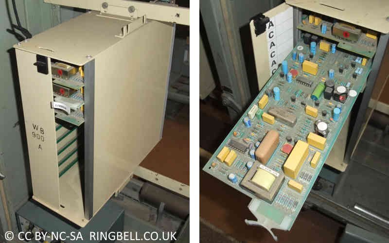
WB900 had nothing to do with the Cold War but was a system for connecting two customers to one pair of wires to overcome shortages in the underground cable network. This provided a better quality of service for customers who in the past were forced to have party lines, or Shared Service to use its correct title. The exchange unit can hold 10 slide in units, each combining two customers in one pair of wires.
Exchange: WB900 Shelf and Line Card
The first customer's line worked exactly as before except that it was diverted to run through the WB900 line card in the exchange. The second customer's line is wired to a separate connection on the line card. This connected it via a carrier system over the first customer's wires. A 64 kHz carrier takes the speech and ringing signals to the second customer. A 40 kHz carrier from the second customer carries the speech, off hook and dialling signals towards the exchange. There is complete privacy between the two customers who could both use their telephones at the same time. The battery in the remote carrier unit in the second customer's house was trickle charged over the line.
Everything about this system was wrong.
It was not a Wire Broadcast (WB) system as it carried signals in both directions. By definition broadcasting is unidirectional.
The engineers who had to work with it hated it, as it was fault prone.
If either customer left their phone off the hook to stop incoming calls the carrier customer's battery went flat.
Engineers were advised that customers must not be told they shared a line as they paid full line rental and may confuse this with shared service on a reduced rental. The highly unpopular shared service which was in abundance in those days offered no privacy between the two customers sharing the same line.
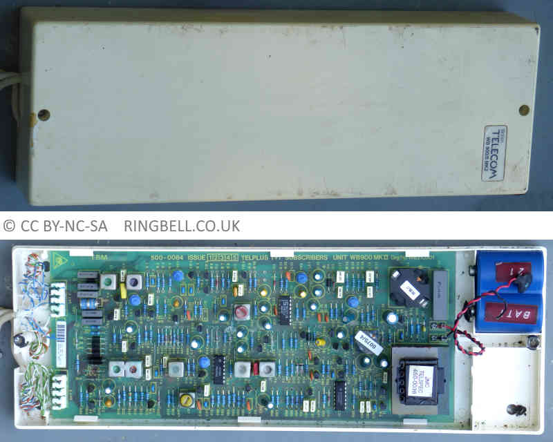
WB900 Carrier Customer Equipment
This picture shows the external appearance and internal printed wiring board of a "Subscribers Unit WB900, Mk.II (Telspec)" Diagram WB210301. It converts the carriers to and from the exchange into the usual analogue conditions expected by a normal telephone. This later version can be either line powered or to prevent the problem of a customer leaving their phone off hook, a mains power adapter is normally fitted.
The other customer, known as the audio customer has no extra equipment fitted in their premises so is unaware of it being a bearer for the carrier customer. A filter to separate the two lines is normally fitted at the distribution point (DP) often at the poletop.
Alarms By Carrier (A.B.C.) WB1000
First mentioned in the 1966 G.P.O. Engineer-in-Chief Report, the system was eventually deployed in East Anglia in 1978
The GPO / BT Alarm By Carrier system, was known internally as WB1000, developed in the late seventies, and marketed as a means of extending burglar and fire alarms to central monitoring points. It replaced the rather unreliable 'Home Office' alarm panels installed at police or fire stations.
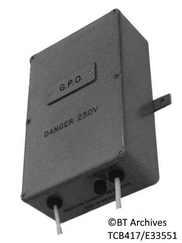
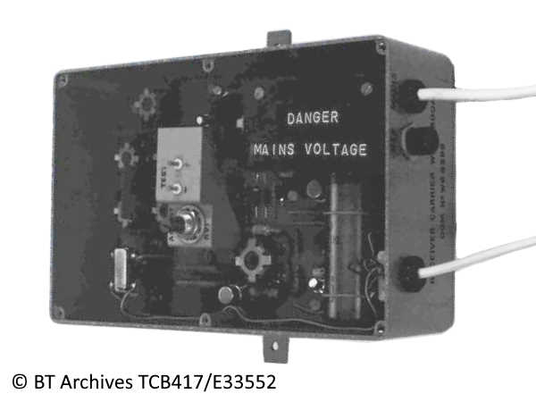
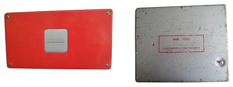
Early Version of Alarm Box and Protective Cover
The red plastic control box was installed inside the grey metal box for protection. The outer box has an anti-tamper switch activated by opening the front panel or by forcibly removing it from the wall.
A.B.C. uses carrier frequencies sent over one of the premises existing telephone lines to communicate with a collector unit in the exchange. Its benefits include: Cost saving by not requiring a separate private wire for the Home Office (HO) panel type alarm. Using carrier rather than direct current signaling improved the reliability compared with HO Panels. Dialup alarms either shared a line to the premises, which was a security risk, as a normal phone call would block the alarm. Alternatively an extra dedicated exchange line had to be provided at additional cost. ABC has a circuit fault alarm warning in the event of the phone line being cut maliciously or due to a fault, this feature is not available to dial up alarms.
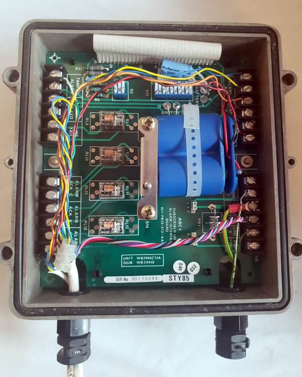
Modern WB1000 Customer's Alarm Box
The eighties version of customer's alarm box [WB1000/74A Diagram WB29910] utilises the standard square die cast box also used by WB1400 power and monitoring units. There are two printed wiring boards and a rechargeable battery. There are three alarm inputs and three alarm acknowledgement outputs. There is a separate Line Fail output. The photos used here of a unit manufactured in 1985 were kindly provided by Ryan White.
A.B.C. was rebranded as 'BT Redcare' in the mid eighties. The high frequency WB1000 carrier system being incompatible with ADSL broadband has been replaced with a system using low frequencies. See http://www.redcare.bt.com/
The Images from BT Archives are Copyright BT Heritage, licensed under a Creative Commons License

 The Images from BT Archives are Copyright BT Heritage, licensed under a