This topic describes the first incarnation of the HANDEL Nuclear Attack Warning equipment and the Wire Broadcast System WB400 Speech Broadcast and WB600 Siren Control. The introductory page "The British Nuclear Warning System" should be read beforehand to gain an understanding of the context for WB400. A separate page describes the successor system WB1400. Both accessible from the Chapter Menu.
HANDEL for WB400
At the time of the introduction of WB400 and HANDEL in the early nineteen sixties, the speaking clock was sourced from telephone exchanges in London and Liverpool with two duplicate clocks at each location. Each clock was a mechanical device based around multi-track magnetic recording on a drum, replaying small sections of the time message, all strung together to form a complete message every ten seconds.
The Speaking Clock Mechanism
HANDEL is the acronym for the system utilising the GPO Speaking Clock distribution network to distribute the attack message across the UK. As in WWII local police stations were responsible for disseminating the warning to the public. This was done by a Carrier Control Point (CCP) in 252 selected locations mainly in police stations.
HANDEL Control Circuits to the Speaking Clock
In the first generation of HANDEL used with WB400, any warning message would be prefixed by P+Q tones of 2400Hz and 2600Hz to set off the alarm on the Carrier Control Points (CCP) in police stations around the U.K. For engineering test purposes, at 08.30 GMT precisely every morning, the usual 1000 Hz pips of the speaking clock were replaced by ones of 2500 Hz, chosen to be midway between the P and Q frequencies. Telecom Instruction E9 E2091 states these special pips should measure -5dBm on a peak program meter to ensure the apparatus functions correctly.
Control of HANDEL was performed by Home Office personnel collocated in the Air Defence Operations Centre (ADOC) who would initiate the attack warning message. If they weren't available at the time of the attack RAF staff would use the HANDEL equipment. Should the ADOC be rendered inoperable the United Kingdom Warning and Monitoring Organisation (UKWMO) HQ in Preston could trigger the attack warning.
In 1963, each of the two control centres, (known to the GPO as Injection Sites) each had one Private Wire ( PW ) to each of the two speaking clock distribution centres located at Faraday Exchange, 136-144 Queen Victoria Street, London EC4V 4BU and Liverpool Central, Lancaster House ATE, Old Hall Street, Liverpool L3 9PY. This was later increased in 1967 to two PWs (Main and Reserve) to each clock switching centre as shown in the diagram. The GPO circuit diagrams for AT60281, AT60282 and AT60283 refer to them as being part of the speaking clock distribution, but for security reasons, no mention of HANDEL.
The clocks themselves were located in Liverpool Central Exchange and Kelvin House, Judd Street, London WC1H 9NP . In 1977 a third clock generator was added at Temple Exchange in 34 Bow Street, Covent Garden, WC2E 7DL. This third clock, not shown in the diagram, was wired to both the London and Liverpool distribution centres for back up.
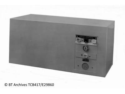
No photographs of this first generation of control equipment has been found in the archives, but researchers at Dundee ROC Sector Museum found a description in the National Records of Scotland HH51/224 from 1963.
1. Purpose The HANDEL equipment enables air attack warning messages (or messages cancelling attack warnings) to be broadcast simultaneously to Carrier Control Points throughout the country. The following instructions set out the action to be taken when the Warning and Monitoring Organisation is activated in an emergency.
2. Preparation (i) OBTAIN THE MASTER KEY FROM THE A.D.O.C. DUTY CONTROLLER (ii) INSERT THIS KEY IN THE LOCK OF THE MAIN CONTROL PANEL AND TURN TO A HORIZONTAL POSITION (iii) CHECK THAT "SYSTEM ON" APPEARS IN THE INDICATOR WINDOW - The system is now ready for use.
3. To Issue Warning (i) PULL OUT AND DEPRESS THE "SPEAK" KEY AND HOLD IT DOWN (ii) AS SOON AS "SPEAK NOW" APPEARS IN THE INDICATOR WINDOW, SPEAK INTO THE MICROPHONE GRILL IN THE CENTRE OF THE CONTROL PANEL
The paragraph explains the "Attack Warning Red" or cancellation message "Attack Message White" should be repeated five times.
When the "SPEAK" key is depressed two check lamps light up. During a transmission the two voltmeters on the control panel should respond to the message being sent. If a second warning Officer is available he should listen to the pair of monitoring receivers to confirm that the message has been broadcast. -BUT- Because of the duplication of the equipment within HANDEL system the failure of one check lamp, voltmeter or monitor receiver to operate does not necessarily mean the whole system has failed. The warning announcement should in any case be made as soon as the "SPEAK NOW" indication is given.
4. Reserve Equipment Reserve operating equipment is provided immediately beneath the main panel and should be used:- if the normal control panel is known to be faulty; if the "SPEAK NOW" indicator on the main panel fails to light after the "SPEAK" key has been depressed; or to reissue a warning if the absence of any response by the two voltmeters or the monitoring receivers shows that a message issued through the normal panel has not been broadcast.
The reserve panel has only the essential controls and is operated as follows;-
(i) INSERT THE MASTER KEY IN THE LOCK OF THE RESERVE PANEL, AND TURN IT TO A HORIZONTAL POSITION. THE "SYSTEM ON" LAMP ON THE RESERVE UNIT WILL LIGHT.
To issue a warning:
(ii) LIFT THE TELEPHONE MOUNTED ON THE RESERVE UNIT, PULL OUT AND DEPRESS THE SPEAK KEY ON THE RESERVE UNIT AND HOLD IT DOWN. (iii) WHEN THE "SPEAK NOW" INDICATOR LAMP ON THE RESERVE PANEL LIGHT, SPEAK INTO THE TELEPHONE.
To make a broadcast, one of the control centres (Injection Sites) operate their speak key, causing the signalling generator [AT60282] to send a burst of P+Q tones along all four Private Wires to activate the signalling receiver [AT60281] that starts a sequence in the switching equipment [AT60283] to disconnect the clock and connect the control centre to the distribution rings. Before switching over to the control centre PW voice circuit, the equipment sends a burst of P+Q out over the clock distribution rings to trigger the police station's CCP alarm.
At the end of the broadcast, releasing the speak key in the control centre, sends a burst of P+Q tone followed immediately by a burst of Q tone along each PW. This sequence disconnects the Injection site and restores the speaking clock.
At each of the clock switching centres, a manual changeover arrangement allows engineers to patch the clock from the other location onto it own rings, thereby maintaining two feeds albeit from the same clock over the duplicated distribution rings. Should HANDEL be operated while this is in place, signalling regenerators [AT60281] in the feed from the other clock, retransmit the P+Q signals to ensure they are received at the correct sound level at the police station.
The signalling receivers used for HANDEL, are modified receivers originally designed for use on overseas telephone circuits in the Trans-Atlantic cable ( TAT ) which used the same tones of 2400 and 2600 Hz for signalling, they didn't reinvent the wheel.
Carrier Control Point (CCP) - WB400 Era
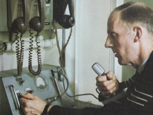
Police Operating the WB400 CCP
This photograph taken from the UKWMO booklet shows the control panels at the Police Station being operated by a sergeant. This was the business end of the equipment comprising the Carrier Control Point (CCP)
WB400 CCP
The control panels in the office are wired back to the telephone apparatus room in the police station. In the apparatus room are two steel cabinets, each 1ft 2in deep x 1ft 10in wide x 6ft high containing the bulk of the electronics shown in the CCP Block Schematic below. A colour photograph of the cabinets appears further down this page.
One apparatus room cabinet contains a spare voice broadcast message controller, the Operating Unit WB 400A, which can be moved into the office should the working unit go faulty. If the office is damaged by the attack, messages can be broadcast from the cabinet in the apparatus room. The power sirens can also be activated from the other cabinet in the apparatus room.
Carrier Control Point Control Panels
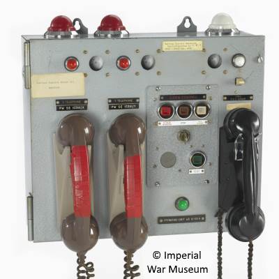
Operating Unit WB401A$
The Operating Unit WB401 is for the receipt of incoming messages and siren control. The control unit has X and Y HANDEL handsets (wrapped in red insulating tape) for listening to the national warning messages.
Each has an associated warning sounder and two red alarm lamps, the larger is mains operated and the smaller one being battery operated. In peacetime, the speaking clock can be heard when lifting these handsets, confirming the circuits are working. The black handset on the right is for two way conversation with ROC Group Headquarters. Incoming calls trigger the sounder and two white alarm lamps. An associated cream coloured flick switch calls the ROC HQ.
The photo gallery contains a black and white image of the unit having older black Bakelite handsets on the HANDEL phones as well as the ROC phone. There are photographs of the internal wiring of that panel too. A centrally mounted plate, the Control Unit WB600, holds the siren master lock switch, three illuminated siren buttons and a test button. Behind the grille is an earpiece so the operator can hear the siren control signal tones being transmitted. These parts can be seen more clearly in the image gallery.
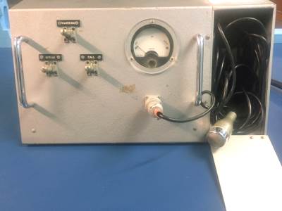
Operating Unit WB400A$
This photograph of the Operating Unit WB400 Mk2 was kindly provided by Gavin Saxby, is one of two units at each CCP, the spare being housed in one of the equipment cabinets in the apparatus room. This unit has two keys to control the Call and Warning signals that precede a warning message.
A Speak key, activates the microphone which is normally housed behind the drop down cover. The meter indicates the correct voice level when broadcasting messages. In the Mk1 version of this unit shown in the gallery the microphone is clipped to the outside of a smaller case. The gallery contains an image of the internal wiring and extra controls on the backplate.
The unit contains three printed wiring boards, a microphone amplifier, tone generator unit (for monitor tick, call and warning sounds) and carrier receiver to drive the modulation meter and miniature speaker.
Block Diagram of the CCP
CCP Block Schematic
The CCP is connected to the Control Point Exchange (CPE) by two pairs of wires, shown leaving the right hand side of the schematic. These are identified as the X and Y paths. Each pair carries audio messages from Strike Command distributed via the speaking clock system, they return the carrier signal back to the CPE for distribution around the area.
The two grey (with Red Tape) HANDEL handsets, mounted on the "Operating Unit WB401A" are connected via amplifiers to the two audio feeds from the Control Point Exchange. To alert the Carrier Control Point, two simultaneous tones of 2400Hz and 2600Hz known as P and Q tones, precede a warning message, the P+Q detector triggers the lamps and sounder above the HANDEL phone. The alarm continues until one handset is lifted. Being a broadcast system there is no facility to talk back to Strike Command or between Carrier Control Points. The speaking clock can be heard on the X and Y path HANDEL phones when a broadcast is not in progress.
Not shown on this block schematic is the third Black handset connecting the CCP with the UKWMO Group Headquarters warning switchboard. Fallout messages from the Group are relayed onwards to the warning points. The police station can initiate a call to the ROC by operating the call button. In either case, the police can have a two way conversation with Group.
Warning messages are broadcast over the WB400 system from the "Operating Unit WB400A", consisting of a microphone, modulation meter and a number of keys on a sloping fronted box. The keys send pulsating tones before each spoken message. One sound was known as "Call" and the other "Attack Warning" the later must not be confused with the attack warning siren control signal which is something completely different. A "Monitor Tick" sound, like a ticking clock, is generated whenever there are no voice messages or siren signals in progress. Further down this page, a recording of a routine test message carries all these signals.
The signals are specified as : Monitor Tick, 12 cycles of 1 kHz with a pulse repetition rate of 90 per minute. Call Signal : A Dot of 12 cycles and Dash of 50 cycles of 1 kHz tone repeated at the same speed as the monitor tick. Attack Signal : 1 kHz signal varying in frequency 140 cycles per minute.
The "Operating Unit WB400A" is normally plugged into the "Working" multiway connector wired back to the working side of the carrier generation equipment housed in an "Equipment Carrier WB404A" located in the police station's telephone apparatus room. Another multiway connector marked "Reserve" is wired back to the reserve side of the carrier equipment. In case of a fault developing, the office's operating unit can be unplugged from the working and plugged into the reserve side connector. A spare "Operating Unit WB400A" is housed inside the "Equipment Carrier WB404A" cabinet located in the apparatus room and kept plugged into the reserve side equipment. This may be used in situ or moved into the police station office.
The output from both working and reserve carrier generators are monitored, if the working side fails, the reserve will be switched in automatically to maintain the carrier signal. This protected carrier feed is divided in two and sent out on the two separate paths (X&Y) towards the Control Point Exchange.
Siren Control
The siren control part of the system was added a few years after the installation of the WB400 and was confusingly designated WB600 as both use the same carrier and share the distribution network. In the apparatus room, the second steel cabinet "Equipment Signalling WB400A" which housed the alarm circuitry to detect the P+Q tones for HANDEL had two spare shelves. Two siren sequence generators were retrofitted into these spare bottom shelves.
Police Interface
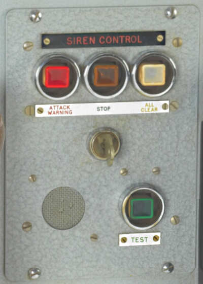
Mounted on the front of the "Operating Unit WB401A" which houses the HANDEL phones, is a small siren control panel known as a "Control Unit WB600A", consisting of interlocking push buttons each containing a small lamp, and a key-switch to prevent accidental or malicious operation. A break glass unit, located close to the CCP, keeps the activating key safe. The circuitry is designed so that each time a siren button is pressed each of the two tone sequence generators will take it in turns to generate the WB600 control signal. A small sounder behind the grille on the unit allows the user to determine if the sequence is running. Therefore if on pressing a siren button, the tone sequence is not heard, pressing the "Stop" button, then pressing the siren button for a second time, will engage the other sequence generator.
Control Unit WB600A
Once the master key is inserted and turned on, pressing either the top left "Attack Warning" button or top right "All Clear" button will activate the remote power sirens. The buttons are illuminated during and after the tone sequence. The central "Stop" button glows orange during the transmission of either signal and goes out when it has finished. After the tone sequence has finished or should the wrong siren button be pressed, operating the "Stop" button will immediately stop any activation signal in progress and release the depressed siren button turning off the button's illuminating lamp.
The lower "Test" button is used by the police to perform silent tests of the control system. The button is non locking and glows green for the duration of the test sequence. The master switch does not need to be operated for a silent test.
Siren Control Sequence Generation
In the apparatus room cabinets, duplicate "Unit Signalling WB600A" take it in turns to generate the tone signals used to modulate the WB400 carrier. The audio signal from whichever is the active sequence generator is fed into both the working and reserve WB400 Modulators.
As a safeguard against failure of the single unduplicated "Control Unit WB600A" in the police office. Each of the two "Unit Signalling WB600A" has a set of siren control buttons and a key-switch mounted on its front panel, enabling the sirens to be controlled from the apparatus room if necessary. The "Stop" button illuminates on the signalling unit that is generating the control sequence, whether triggered by the control unit in the police office or locally with the buttons on front of this signalling unit. A locking "Hold" button which glows when depressed is fitted instead of the "Test" button. The "Hold" button is used to lock one particular signalling unit into working mode should the other unit become faulty.
Unit Signalling WB600A$
Remote siren receivers are controlled by two audio tones generated by the signalling unit, a guard or "G-signal" of 1500Hz and siren activation or "S-signal" of 2160Hz. To prime the siren receiver, the G-signal is pulsed 0.4 seconds on and 0.4 seconds off for 10 seconds. This is followed by the S-signal whose duration depends on the message being given, pulsing 4 seconds on and 4 seconds off, for the "Attack Warning", or 60 seconds continuously for the "All Clear".
Demonstration of Siren Control Signals
Description:
This is a Stereo recording, so it is better to listen with headphones. The WB600 Siren Control tones are on the left channel. The siren sound it is on the right channel so that you can appreciate the relationship between the siren and the tones.
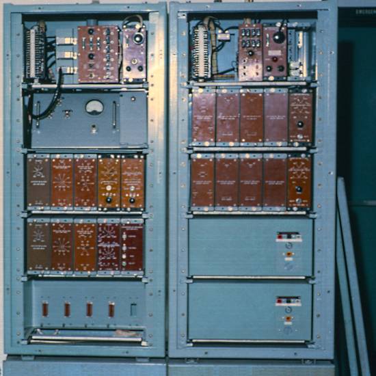
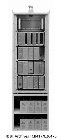
CCP Equipment Cabinets
The electronics needed to make the CCP control panels work were very bulky and heavy by today's standards, the total weight being approximately 900 lbs. (8 cwt / 400 Kg).
The two cabinets were usually located in the telephone apparatus room, although in the case of the CCP featured here, they were next to the CCP Control units. The left hand cabinet 'Equipment Carrier WB404A' housed the WB400 speech broadcast part of the CCP. The right hand cabinet 'Equipment Signalling WB400A' contained the HANDEL incoming call detector and the WB600 siren signal generation part of the CCP. The bolt on covers have been removed and stood against the right hand cabinet.
Equipment Carrier WB404A and Equipment Signalling WB400A Cabinets at a CCP
Roll your mouse over the photograph for a description of the item.
-
Police Routine Functional Test
Speech Receivers
Every six months the police performed a test of the speech broadcast system. Before the test each Warning Point was sent a card advising them of the date and time of the test. This had to be completed and returned to the police liaison point who reported any faults to the telephone fault repair service. The link below has a recording made by Bob Pickwoad at Newick ROC Post during one such test in 1966/7. I am very grateful to Bob for offering me a copy of the recording for this site in 2005.
Remote Siren Test
Regular testing of the siren receivers were performed by the police, using the 'Test' button on the Siren Control Unit at the CCP. This did not sound the siren but lit a small lamp. Over the next few days, the 'War Duty' police officer would visit the siren locations and check that the test lamp was illuminated and report any faults.
Contractors, usually the electricity board, visited the siren switch panels to test them and 'flick test' the siren. By briefly applying power the siren would be heard to growl, but it was not allowed to get up to warning speed.
Control Point Exchange (CPE) - WB400 Era
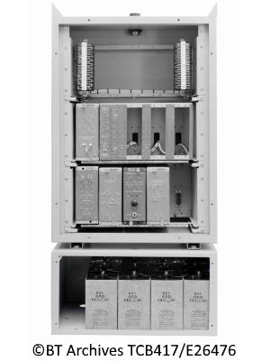
CPE Hardware
The Control Point Exchange (CPE) is located in the public telephone exchange that serves the Carrier Control Point (CCP). The photograph from the archives shows the CPE hardware in the exchange, a grey steel protective cabinet known as an Equipment Carrier WB405A. The enlarged version also shows cabinet with its screw on front cover fitted. The cabinet is mounted on a Box, Battery WB401A having a matching screw on cover. Depending on the number of distribution amplifiers fitted in the cabinet and other factors, the battery box may contain, 12 or 24 large dry cells (Cell, Dry WB401A) approximately 4½" square and 8" high, or for larger loads, 12 huge dry cells (Cell, Dry WB400A) in two tiers, each cell is 6⅝" x 6⅝" x 8¼" high, weighing 15½ lbs (7 Kg)
The actual dimensions of the CPE hardware: Equipment Carrier WB405A, 1′-10½″ wide, 1′-0½″ deep, height above battery box 4′-1″. Weight empty 175lb, plug in units 35 - 55lb. Box Battery WB401A, 1′-10½″ wide, 1′-2″ deep, 1′-11″ high. Weight empty 40lb, adding 12 x Cells, Dry WB400A at 185 lbs or 24 x Cells, Dry WB401A at 170 lbs.
CPE Block Schematic
The CPE equipment is connected to the CCP at the Police Station by two pairs of wires, shown leaving the left hand side of the schematic. These are identified as the X and Y paths. Each pair of wires to the CCP transmit audio messages from Strike Command in one direction and received the carrier signal for amplification and distribution.
The exchange receives two feeds from the Speaking Clock distribution rings. Each is split to serve both the Civil Defence CPE equipment and the public speaking clock. In the public speaking clock each of the two feeds are amplified with one working (serving customers) and the other on standby (to a dummy load). Should either feed fail an exchange alarm will be raised and the other amplifier used instead. Should both fail then Number Unobtainable Tone is be connected to anyone dialling the clock, they would not be charged for the call. During the Cold War period after the introduction of STD, the speaking code was 8081 and 123 in large cities. This was standardised nationally to 123 in April 1995 when the analogue speaking clock rings were decommissioned.
The audio from the speaking clock feed is amplified in the CPE equipment and sent down the X and Y path towards the CCP at the police station. The same X and Y path wires bring the 72kHz carrier signal back to the CPE. In case one path should fail the two carrier signals were monitored in a change over unit. This protected feed was amplified and fed the local warning points and also be sent over inter exchange junction circuits to other remote exchanges for distribution to their warning points too.
Carrier Distribution
The Carrier Control Point (C.C.P.) generates two identical carrier feeds sent over the X and Y path to the Control Point Exchange (C.P.E.). In the diagrams these are shown in Red and Blue.
Carrier Distribution Network Between Exchanges
In the 1960-70 era, many villages only had a single underground cable feeding the exchange, so there was little point in duplicating their carrier feed. In more remote locations, one cable passed through a number of exchanges. In the diagram above, village C is supplied from village B. There were design rules that limited the number of tandem links that could be used. Quite often a small village may have only have had one or two warning points to feed.
If it is desired to extend the dual paths beyond the C.P.E., perhaps to other large towns within the warning district, then two additional amplifiers are fitted on the dedicated X and Y paths. These amplifiers feed distribution panels to extend the X and Y path to other dual fed exchanges. In the example above only one such exchange is shown as the 'Large Town', but in reality there may be a chain of dual fed exchanges. To guard against damage to the underground cables, the X and Y paths are kept physically as far apart as possible.
Swindon Carrier Area
In the Swindon Carrier Area, the dual path runs from Swindon through two small exchanges to Marlborough. All other exchanges are single fed. The way the exchanges are fed in tandem reflects the route of the cables in the area. The two or three letter group inside each exchange circle is the THQ1141 code for that exchange.
At all dual fed exchanges including the C.P.E., a changeover unit monitors the two incoming carriers. Should one fail, it selects the other. This switched supply (shown in Black) is amplified and distributed to the Warning Points in the town. If it is necessary to extend the distribution onto further exchanges, these too are single fed from the switched supply.
The Distribution Cabinet$
The first photograph in the gallery (taken at the Avoncroft Museum, Bromsgrove) shows the Equipment Carrier WB400A and Box Battery WB400A. This protective cabinet, used at single path dependent exchanges, houses the amplifiers and distribution units. The other B/W slides from the BT Archives shows the internal arrangements in the cabinet.
The actual dimensions of the Equipment Carrier WB400A is, 1′-10½″ wide, 1′-0½″ deep, its height above battery box is 2′-8″. An empty weight of 115lb, with the plug in units adding 15 - 25lb.
Box Battery WB400A is, 1′-10½″ wide, 1′-2″ deep, 1′-0¼″ high. Weight when empty 35lb, the twelve dry cells adding a further 85lb.
The cabinet has a standard layout, but the type and quantity of Distribution Amplifiers fitted, varies from exchange to exchange, depending on the number of customers served. The battery box below houses the large dry cells, twelve in all, acting as backup should the exchange's 50 volt battery supply fail following a prolonged mains failure, as may occur in a war situation.
The provisioning rules are laid out in Telecom Instruction A8 J1053, part is shown in the gallery. There are two types of amplifier modules, a single output type and a dual output type. Archive images of both types are in the gallery. Each amplifier output can feed a maximum of 25 customers circuits, via five Distribution Unit WB400A. Depending on the length of line, a low-level or high-level supply is needed. One high level supply is the equivalent of five low level supplies, this affects the maximum number of feeds that one amplifier output can supply. These interdependencies make planning a complex task.
In the mid-eighties when the WB1400 replaced the WB400, the protective cases were retained and refitted with shelves holding the new smaller electronics.
Local Distribution to Warning Points
The telephone line going to the warning point was used to convey the WB carrier to the receiver or siren. In the 1960 - 70 period, lines were often in short supply, waiting lists for phones were not uncommon and two customers may have shared the same pair of wires back to the exchange in what was known as shared service or party line. Sending the carrier over the existing phone line removed the need and expense for an extra pair of wires to the warning point.
Exchange Feed
Exchange Feeding the Receiver
In the WB400 equipment cabinet at the exchange, the carrier was amplified and divided into a number of individual supplies, one for each warning point. A connection is made from the carrier distribution unit to the line towards the customer. To prevent the exchange's line circuit from shunting the carrier, the wiring is routed via an inductor unit then out to line. Inductors block the passage of the higher frequency of the carrier whilst still allowing the voice, direct current and ringing for the telephone through.
The gallery below shows the two different ways the blocking inductors were connected into the customers line. In the early days of telephones, most lines were overhead and risked contact with mains electricity which was often distributed on overhead wires. Exchanges were fitted with protection devices to prevent lighning strikes or contact with mains electricity from damaging the exchange equipment. 10mH inductors cased in a small two part Bakelite case 60 x 12mm (Inductor 120CN) were fitted to the protection and test jacks.
By the sixties there were less uninsulated overhead wires so a more modern exchanges were fitted with compact test jacks without any extra protection. This necessitated a different arrangement to connect the inductors to the customer's lines. An Inductor Unit WB1A was developed containing 16 pairs of inductors, through which WB400 / WB600 customer lines were connected.
Exchange Line Inductors$
Individual Customer Wiring
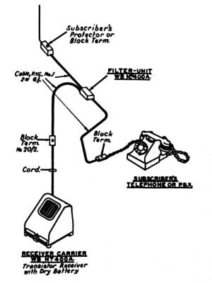
In the early sixties when Bakelite telephones were in use, a filter unit made from Bakelite to match the phone was used to separate the carrier signal from the telephone circuit. The gallery shows the components of a typical receiver station, comprising of the filter unit, the carrier receiver and the basic Bakelite table top telephone.
Basic Receiver Station$
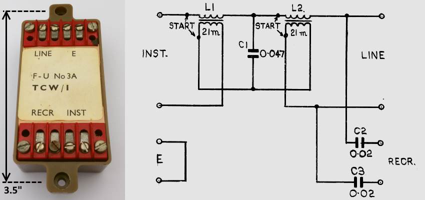
When coloured plastic telephones replaced the old fashioned black Bakelite models, the opportunity was taken to remodel the filter unit into a plastic case. The older Filter Unit WB400 was electrically identical to the Filter Unit 3A and may have remained in use if the customer decided to upgrade their old black telephone to a modern coloured model. For new installations of plastic telephones, the Filter 3A would be fitted.
WB Filter Unit 3A and Circuit Diagram WB28680
At the warning point, the telephone (telephone instrument as they were called) is wired via a 'Filter Unit 3A'. This separates the speech, line current and ringing from the LINE and sends it to the INSTrument connection whilst blocking the carrier, this stop the telephone from shunting the carrier.
The filter's other connection point RECeiver has the opposite effect, it only allows the carrier to pass and blocks everything else, so the presence of the receiver does not affect the operation of the telephone.
Distribution within Buildings
In large industrial premises the siren or speech receiver may be situated in a part of the building remote from the point where the telephone lines enter the building. In these type of premises there would be a number of incoming exchange lines to the company's switchboard or Private Automatic Branch Exchange ( PABX ). The Warning Receiver may need to be located in a permanently staffed room such as a security office away from the switchboard. It was necessary to convey the carrier signal to that receiver. Although the use of a dedicated pair of wires was a possibility it represented a fault liability so often a nearby extension telephone line was utilised.
Bypassing around a Switchboard
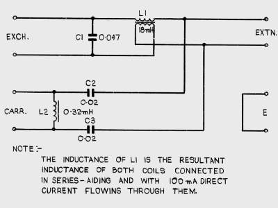
The carrier could not pass through the switchboard or PABX so it had to bypass it. This was done with a 'Filter Unit 3A' separating the 72kHz carrier being sent over a designated exchange line. The carrier signal was reintroduced back onto the selected extension line with a Filter Unit 4A as shown in the diagram above. This would wend its way through the building. A further Filter Unit 3A located near the telephone extension separated the carrier to feed the receiver. In the diagram, the wires carrying the carrier only are marked Green, those with telephone and carrier are Red, telephony only wires are coloured Black.
WB Filter Unit 4A, Diag. WB28681
The 'Filter Unit 4A' allows easy passage of the carrier from the CARRier to the extension ( EXTN ) whilst blocking it from going towards the EXCHange (The switchboard). Audio, ringing and direct current to energise the telephone extension pass easily between EXCH and EXTN but are blocked from going to the CARR terminal and causing overhearing between the exchange line and extension.
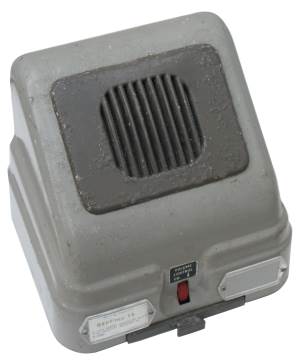
WB400 Carrier Speech Receiver
WB400 Receiver$
The WB400 receiver is powered by a Six volt battery (Battery Dry No.27) in the base. Specified as being capable of supplying 10 milliamp continually for not less than two months, after standing idle for up to a year. A photograph of this battery, which is sized 6″ x 5½″ x 1½″ appears in the gallery. Spare batteries were provided and it was expected the user would change them when necessary by removing the baseplate with a coin.
When correctly adjusted the receiver should emit a quiet tick like a clock, of the monitor tone sent by Carrier Control Point. The audio volume increases automatically for a calling signal or speech message.
In peacetime the receiver was normally switched off and only turned on for tests. The red knob on the front is a combined On/Off and Volume control. Below that is a small pull out draw containing an instruction card telling the user what to do in response to a message and how to change the battery. The card is reproduced in the Topic below.
A number of large images can be found in the Gallery, illustrating the exterior and interior components of the Receiver Carrier WB400.
To protect the electronics from moisture, the chassis plate has a cork seal and a plastic membrane covers the speaker grills. A desiccator unit helps absorb any moisture ingress, this is fitted to the chassis plate so it may be viewed from the battery compartment. Normally Blue, the colour changes to Pink if damp gets in.
The receiver has two printed wiring boards, the radio frequency board which amplifies and detects the audio on the 72kHz carrier can be identified by the four square aluminium cans. The other is the audio board which has a pre-amplifier and suppressor to reduce the output when the monitor tone is being received. Next to the audio board is the output transformer with the two output transistors mounted on its tags.
On many occasions the user would forget to switch it off after the six monthly test message and flatten the battery. When the replacement system was designed, changing batteries were no longer necessary as the power was fed from the telephone exchange. It seems strange though, it was still necessary to turn the receiver on when required as this was not done automatically.
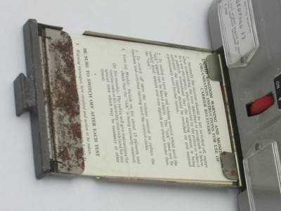
WB400 Warning Point User Instructions
WB400 Instruction Card 1968$
Instructions for the Warning Points are printed on a small folded card held in a drawer in the base of the WB400 receiver unit.
The four pages of the card are reproduced in the gallery to you can read the detail. A printable version suitable for collectors who may own a WB400 receiver may be found in the Document Library - WB Documents section by using the website menu.
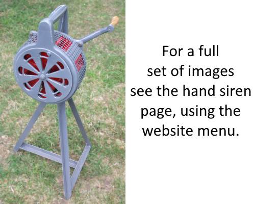
Hand Operated Siren
Electric Mains powered sirens were usually confined to towns and cities. The mains operated sirens are described in detail on the siren page.
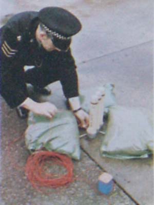
Warning points in rural areas without power sirens had a hand operated siren like the one photographed to sound the Attack Warning and the All Clear signals.
In this picture of a policeman preparing to give a fallout warning, using a maroon, a firework that shoots up a shell which explodes around 100ft with a very loud bang. The maroon in the photograph is held in place with sandbags and operated remotely with a battery. Once triggered it sends up three maroons spaced a few seconds apart to give the BANG, BANG, BANG fallout warning. The policeman may also give three blast with his whistle too.
Fallout Warning Maroons
Receiver Circuitry
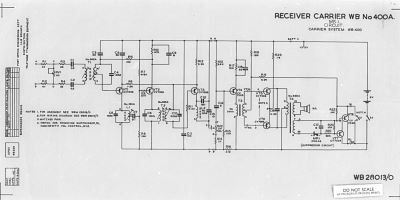
WB400 Receiver - Diagram WB28013
The WB400 Carrier Receiver (Diagram WB28013) employs Germanium junction transistors reflecting the technology when it was designed in the early nineteen sixties. The RF board has three CV7005 (OC71) transistors, the audio board one more CV7005 with two CV7006 (OC72) output transistors and two CV7004 (OC45) in the squelch. Transistors VT1 and VT2 amplify the incoming signal. VT3 is the AM detector that feeds the volume control. The audio push pull output stages comprise VT4, 5 and 6. A small amount of audio is fed into what is called the suppressor circuit. This reduces the gain of the audio output stage when the monitor tick is present so its like a clock ticking. When a spoken message is received the gain is increased so it may be heard clearly.
There was no Electro-Magnetic Pulse (EMP) protection in this receiver or other parts of the system. This is because the equipment was designed and manufactured before the phenomena of the EMP had been discovered. The EMP effect was first noticed in 1962. The American " Starfish Prime " test on 9th July 1962 affected telephone and power systems 900 miles away in Hawaii. A Russian test on 22 October 1962 when a 300kt warhead was detonated at 290km altitude apparently affected 570km of telephone lines and started a fire that burnt down the Karaganda electricity generating station.
The earlier version of the warning receiver using thermionic valves may have had some immunity to the EMP effect. It was field trialled in the fifties but never deployed due to lack of finances. By the sixties, transistors were replacing thermionic valves, as their power requirements were much less, and therefore seen as a great improvement. Transistors superseded thermionic valves by the time the WB400 was designed.
The receiver is simply an AM radio tuned to 72kHz that gets its signal from the telephone line rather than an aerial. Those deployed in areas near to Very Low Frequency (VLF) transmitters operating close to 72kHz could be affected by interference. A special line balancing circuit could be fitted to eliminate weak radio interference. The VLF transmitter at Rugby on 68kHz was one source. In some carrier control areas near to Decca Navigation VLF transmitters (Purple slave) the interference was stronger, it was necessary to change the carrier frequency from 72kHz to 70.5kHz to overcome the problem. These CCPs were Lockgilphead, Campbeltown, Dumphries, Lanark, Motherwell, Stirling, Oban and East Kilbride.
This corresponds to Decca on 70.538 kHz at Stirling, however http://jproc.ca/hyperbolic/decca_chains.html shows transmitters at Wormleighton, Warwickshire on 70.833 kHz; Burton Fleming, Yorkshire on 70.379 kHz and Llancarfan, Vale of Glamorgan on 70.233 kHz. I don't understand why these sites didn't appear to cause problems too. Decca VLF in the UK closed on March 31, 2000.
Siren Point Carrier Receiver WB600
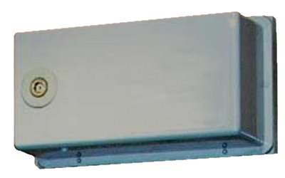
At the siren point, a "Receiver Carrier WB600" a grey plastic box mounted on a steel back plate approximately 16 inches wide by 9 inches high and 6¾ inches deep, has a test lamp with an integral reset switch on an otherwise featureless box. The receiver connects to a telephone line via a "Filter Unit WB600A" allowing a telephone and the siren to share the same line without any interference between the two. The receiver is wired into the Home Office, Siren Switch Panel which provides its power and local control for sounding the siren.
WB600 Carrier Receiver$
Remote Siren Test
The green " Test " button on the CCP's Siren Control Unit (Control Unit WB600A) is used to perform the police regular routine check of the siren system. This button can be used without operating the master switch. When the button is pressed it sends out a special test sequence of G & S signals that cause the test lamp on the WB600 Receiver to light.
Over the next few days, the 'War Duty' police officer visits each siren location and checks if the test lamp on the siren receiver is illuminated then presses the lamp cover to reset and extinguish it. The officer notes any location where the lamp isn't illuminated and reports those faulty to the Post Office telephone repair service.
Siren Receiver Operation
The siren receiver WB28502 circuitry contains a 72kHz carrier receiver similar to that in the WB400 speech receiver. The audio output can be monitored on the back panel checking the WB400 monitor tone tick is present. This audio is amplified and filtered to extract the two remote control signal tones known as the 1500Hz Guard 'G' signal and 2160Hz Siren 'S' signal.
As the WB600 audio control signals modulate the WB400 carrier, warning points can hear these on their receiver, which is mentioned on the warning point instruction card. (See earlier topics) The siren switch panel and power sirens have a dedicated page to the topic. This may be found as 'Power Siren' in the website menu.
To prime the siren circuit, the 1500 Hz guard signal is pulsed 0.4 Seconds on and 0.4 Seconds off, for 10 seconds. Unusually the guard signal pulses are detected by a galvanometer relay or Rhythmatic Relay. This device, which is shown in the gallery, is tuned to a period time of 0.8 seconds, after a few seconds of 'G' signal pulses, the armature rotates far enough to touch an electrical contact. This delay gives the necessary immunity to prevent the receiver being accidentally triggered by the human voice during speech broadcasts.
Approximately 6 seconds of pulsed G-signal primes the S-signal circuitry. The subsequent S-signal operates a small relay, extending mains line voltage back into the siren switch panel to further operate the siren 3-Phase mains contactor. The duration of the 2160 Hz siren signal sent by the CCP controls how long the siren motor is energised for, four seconds on four seconds off for an attack and sixty seconds continuous for the all clear.
The receivers employed Germanium Junction transistors, then cutting edge technology in the nineteen sixties when the system was designed. None of the WB400 or WB600 equipment circuitry contained any Electro-Magnetic Pulse (EMP) protection. After a thunderstorm, it was in my experience, often necessary to replace faulty WB600 receivers especially those in water towers and other high points. After changing the receiver, it was good fun to run the siren for a couple of seconds.
Test Equipment
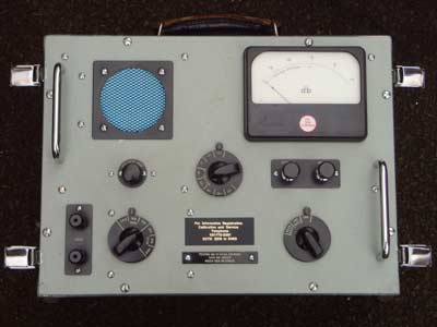
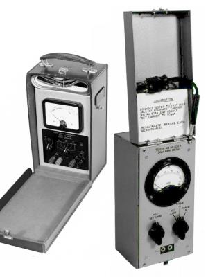
Tester WB400A
Roy has kindly sent this photograph of a Tester WB400A at the 'Ulster Aviation Society Museum'. This tester was used to set the correct carrier signal levels in the CCP and Exchange apparatus and locate faults in the distribution network. It is a Level Measuring Set ( LMS ) tuned to 72kHz that displays the signal strength on the meter in the range of -65 to +25 dB. The unit also contains a speaker unit so the audio modulation could be heard just like listening to a warning receiver. The input terminals are on the bottom left hand side in this photograph. The designation plate shows it was made in 1962 to Diagram WB28029.
The tester WB400A is in a rugged steel box approximately 24" x 18" x 6" and has a detachable lid. It weighs 5 or 6 Kg and I can recall climbing up a telephone pole with mine to locate a fault. I shudder to think what would have happened if I had dropped it on someone!
More WB400 Testers$
The two testers pictured here have been discovered in the BT Archives although I never saw these in use locally during the seventies.
The Tester WB402A [Diagram WB28062] is used to set the modulation depth of the amplitude modulated 72 kHz carrier generated by the CCP.
The Tester WB405A [Diagram WB28214] is a signal level measuring device tailored for the WB400 system with ranges of +15 db at 30Ω impedance, -10 db at 38Ω impedance and -46 db at 140Ω impedance in both the THRO (Through) and TERM (Terminated) conditions.
The Images from BT Archives are Copyright BT Heritage, licensed under a Creative Commons License


 The Images from BT Archives are Copyright BT Heritage, licensed under a