Network Development
Conspiracy Theories
Over the years there has been much speculation about the purpose of the GPO / BT microwave network. It certainly was used for carrying Television, Telephone and Private circuits over long distances. However some authors have suggested devious military or spying purposes which seem very unlikely but cannot be ruled out. One rather stupid idea put forward was the microwave beams being intercepted at Regional Government Headquarters at times of war.
The conspiracy theories have been fuelled by a Cabinet Office paper in the National Archives file CAB 134/1207 dated 1956 proposing a microwave backbone bypassing major cities to safeguard vital communications at times of war, but that planning outline wasn't the reason for developing the main network.
Reality
During the late fifties and early sixties the demand for long distance television links outstripped the provision of the preferred option of coaxial cables, the early growth of the microwave links was for television not the cold war. This wasn't a network but separate point to point microwave links patched together where coaxial cables did not exist and could not be provided in time to meet the broadcasters demands.
Once the surge in demand for television links were met, microwave systems were used to augment the telephony capacity. At the beginning of the nineteen sixties, work started building the strategic 'Backbone' network to safeguard important long distance circuits. Some authors have tried to unsuccessfully fit the concrete towers which were built for aesthetic reasons, not resilience against attack, into the outdated 1956 Cabinet Office plan.
Only in the sixties did a long haul network form. Modernisation of the highlands and islands telephone system in the seventies relied on microwaves to provide connections to local exchanges, but this wasn't part of the national long haul network characterised by 3 or 4 metre dishes on tall towers. The national network continued to grow for a number of years reaching maturity in the early eighties.
Insider's View
Mr L.R.N. Mills former head of PO Inland Radio Planning, writing for Connected Earth - Birth of the BT Tower sums up the position in the early sixties : . . . Thus we had a number of disjointed radio links connected together by cable with no apparent plan for a national radio network. Then came Backbone, a system planned to provide secure communications between strategic Government locations avoiding cables which, by the very nature of the network, passed through important towns and cities. The Backbone network deliberately avoided built-up areas and thus did not provide any basis for a national city to city radio network. Top management in the Radio Branch were somewhat irritated by this. . . . . . . . . Then came, BBC2, 625-line colour television. . . . . . . plans were at last laid for a national city to city microwave radio network. . . . . . . Next question, if a national radio network were established for TV, would adding telephony channels to radio links be cheaper than laying more cables? [Yes] . . . . . . . . The conclusion from all this is that we have mainly to thank the coming of 625-line colour television for the existence of BT's microwave radio network and the [London] BT Tower. And as head of planning he should know.
Design of Towers
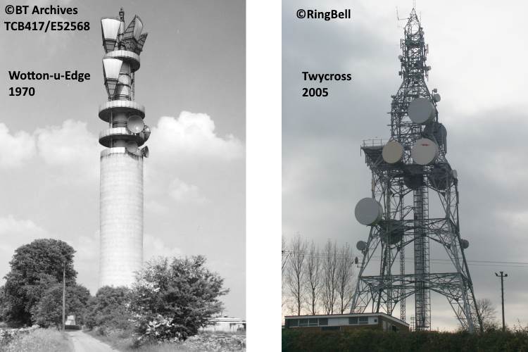
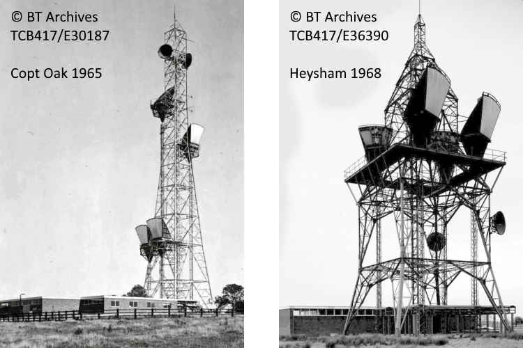
The early parts of the network used microwave dish aerials as seen on the top of Copt Oak tower. Later on microwave horn aerials became the norm as they could provide dual polarisation and dual band working for increased capacity. Developments in dish aerials design allowed their use to become widespread and eventually most of the bulky and heavy horn aerials were replaced by dishes. Modern dish antenna are encased to protect them from the elements, these look like drums, as seen at Twycross above. With the introduction of digital microwave systems in the eighties on the 11 GHz band, the dish size could be reduced slightly.
Microwave links are limited in length by the curvature of the earth as the aerials must be in line of sight of each other. This dictates the spacing of microwave stations and tower heights. The signals are affected by weather conditions and reflections from water if they cross the sea, causing fading. To overcome fading, two dishes spaced a distance apart, so they are affected differently by the changing condition are connected to the receiver, which selects the strongest signal at any instance of time.
The original fifties microwave systems were just a dish on a straight vertical tower. The introduction of horn antenna during the sixties required a different design of tower, tapering towards the top such as Copt Oak. A stepped design, like this at Heysham became widespread. Towers of this type, were not well received in some parts of the country, so ferro-concrete designs were introduced to meet planning requirements. The 1961-2 GPO Engineer-in-Chief's annual report Page 27 comments on the introduction of a standardised design of concrete tower. Wotton under Edge shown here, was one built to the 'Chiltern' design along with Charwelton, Heaton Park, Pye Green, Stokenchurch, Sutton Common and Tinshill. Morborne Hill and Purdown were modified forms of the Chiltern with more aerial galleries. Two bespoke designs of concrete tower were built in London and Birmingham city centres. A one-off design used at Tolsford Hill for the cross channel relay.
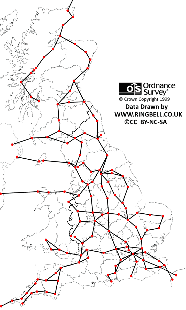
By the time the network had reached maturity in the mid-eighties its tentacles has spread right across the mainland. The network diagram shows only the long haul common bearers. Branching off from these were links to customers sites, mainly television distribution but also a number of radar stations for the Linesman-Mediator system for the Royal Air Force and civilian air traffic control. The diagram omits the Scottish Highlands and Islands communications modernisation microwave links as these were for connections between local exchanges and not long haul traffic. This national network is sometimes called the microwave backbone as it indeed was, but should not be confused with 'Backbone' for important military and civilian circuits, which is explained in the next topic.
The End Game
When Optical Fibre made its way into the BT network providing huge capacity for telephony and especially the growing data market. The relatively low bandwidth long haul microwave network became redundant. During the mid-2000s the long haul microwave dishes were removed from the BT microwave towers leaving some looking very bare. Only those serving the highlands of Scotland still remain in 2018. Microwaves are still used to feed some medium bandwidth customers premises, but with the drive to provide fibre to the customer, their life expectancy is rather short.

 The Images from BT Archives are Copyright BT Heritage, licensed under a