It is essential that telecommunication equipment continues to operate should an emergency or war situation cause the loss of the public electricity supply. During the cold war period all telephone exchanges had a battery reserve but only those in larger towns and in cities possessed a standby generator.
Telecommunications Power
Telephone switching equipment in the UK is powered by a 50 volt direct current ( DC ) supply with the positive pole earthed. From the sixties onwards, repeater station equipment was powered by a 24 volt direct current supply or in some cases 50 volts.
A typical arrangement is shown below, one or more power units, known in GPO/BT terms as a 'Rectifier', converts AC mains into a nominal 50 volt DC. All the rectifiers are connected in parallel to a common busbar. One or more batteries are also connected in parallel across the busbar. This common busbar is extended into the apparatus room to power all of the switching apparatus.
In the large electromechanical exchanges present in the network from the fifties to eighties, the load at peak times of day may be many thousands of amperes at 50 volts. This necessitates large copper or aluminium busbars, grouped together. The 50 volt negative busbar is covered in Blue insulation but the return busbar at earth potential may be uncovered or covered in Red insulation. In both cases the busbars are insulated from the supporting ironwork.
Typical 50 Volt Power Arrangement
The AC Mains supply may be either 240 volt single or 415 volt 3-phase. The rectifier output voltage is tightly regulated so the rectifiers take the majority of the equipment load but also keep the batteries fully charged. The batteries take any instantaneous peaks in demand.
Should the AC mains supply fail, the battery will keep the exchange working for a while. In rural areas, their small exchanges might continue to work for a day or more on their single battery. Exchanges in towns and cities have too large a load to rely solely on batteries. The battery capacity is usually sufficient for 1 hour. Such exchanges have one or more automatically starting diesel generators that can provide the AC supply to the rectifiers and limited other facilities, such as emergency lighting in the building, within seconds of the mains failure.
The WB400 first generation or WB1400 second generation of the early warning system is powered from the exchange 50 volt supply. To guard against this failing, which might happen in a war situation at exchanges without standby generators or if the generator fails to start, the equipment has its own primary cell battery capable of around 4 weeks of duty.
AC Mains Supply and Standby Generator
The type of AC mains supply into a telecommunications building varies according to the load. Small rural exchanges usually have a single phase 240 Volt supply which may be fed underground or on overhead wires. Medium size exchanges, those likely to have a standby generator in the cold war era (nowadays even rural exchanges have generators) would have a 415 Volt three phase medium voltage supply. At large exchanges, the load is sufficient to warrant an industrial high voltage three phase 11,000 Volt feed. Due to the importance of telephone exchanges, this is often from two separate sub-stations.
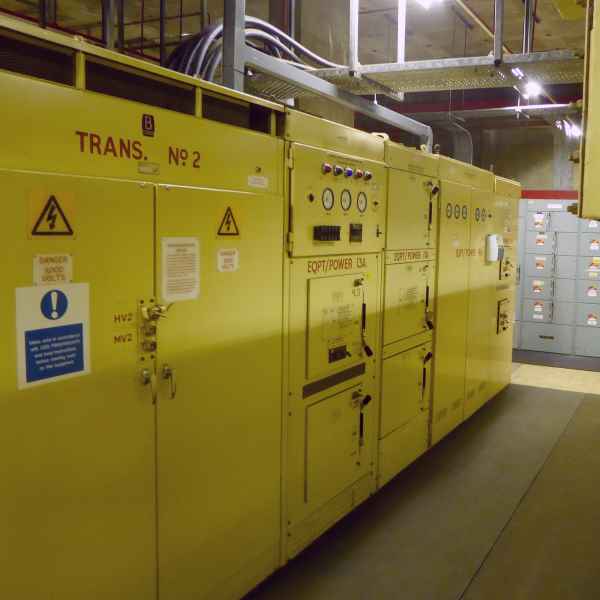
Power Cubicle
This photograph taken through the chain link separating the high voltage area, shows a suit of power cubicles associated with the second of two standby generators. The cubical nearest the camera is an air-cooled 11,000 to 415 volt transformer for the incoming public supply. The subsequent cubicles all operate at 415 volts contain isolators and switching between the generator and the public mains supply.
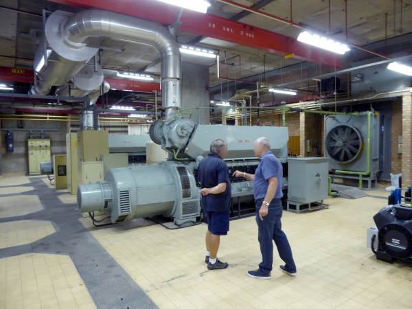
The photograph gallery below shows two standby diesel engines each driving a 550 KVA alternator in a room large enough for a third if necessary. In non-technical language, sufficient to power 1100 single bar electric fires. Not shown in the gallery, are fuel tanks containing a 28 day supply for continuous running in an emergency situation.
Standby Diesel Generators$
Each generator set comprises of a compressed air start, turbo-charged diesel engine driving an alternator and an exciter for the alternator. The alternator produces 550 KVA of three phase electricity at 415 volts. The compressed air for starting is held in large tanks. Each generator set has its own cooling fan for both water and lubricating oil. The oil is stored in a large tank beside the engine.
The Engine Control Cubicle, one per generator, an 'Equipment Power No.9A', detects the mains fail and mains restored condition and starts or stops the engine. It also monitors for fault conditions that might affect the safe running of the equipment. It has facilities to allow the maintenance staff to test these fault conditions are correctly identified and to run the engine, even when the public mains supply is present.
Standby Battery
During most of the cold war period, analogue exchanges predominated in the network. These favoured a centralised power scheme requiring large power units and battery reserves distributed by large busbars around the apparatus room. Early digital exchanges continued with this arrangement. As the digital network developed, exchanges moved towards a distributed power scheme, where groups of racks were powered by a Power Equipment Rack (PER) still producing a nominal 50 volt output but consisting of a number of small capacity power units running in parallel and a small reserve battery. This mimicked the larger centralised scheme but on a much smaller basis with many PERs per exchange. Whatever the type of 50 volt source, digital switching racks contained numerous power converters, taking in 50 volts and producing the low voltages required for integrated circuits and microprocessors.
Lead Acid Cells in Lead Lined Boxes
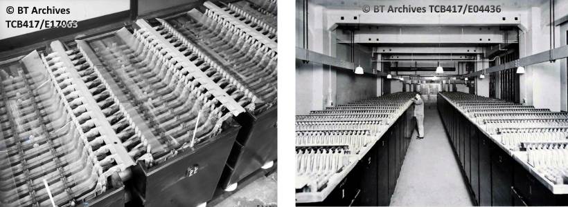
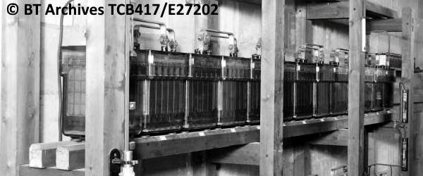
The exchange 50 volt battery consists of 24 separate lead-acid cells joined together in series. The positive group of plates in one cell are electrically bonded to the negative plates in the next. Originally these cells were housed in lead lined wooden boxes and filled with Sulphuric Acid. The lead plates are suspended on glass rods and interleaved positive and negative across the width of the cell and fully immersed in the acid.
The right hand photograph shows two separate batteries with a gangway between. The size of each cell can be judged by the engineer inspecting the specific gravity of the acid, which is used to determine the percentage of charge in the battery. Due to their long life, batteries of this type existed well into the seventies even though more compact glass vessel batteries were being fitted in the sixties.
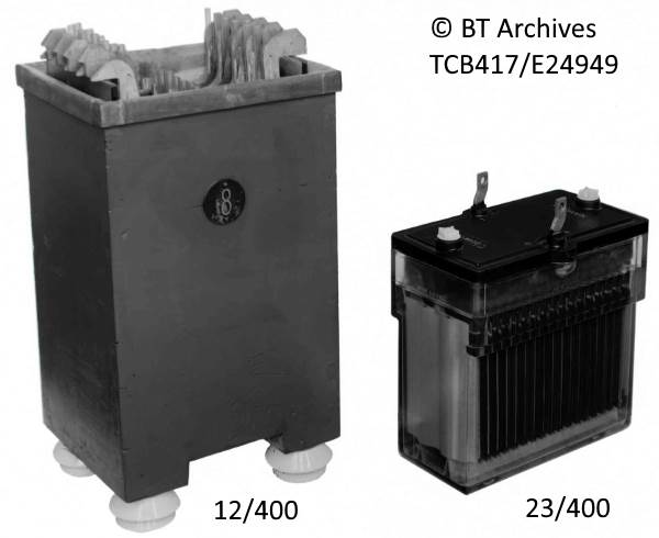
Two Types of 400 Ah Cells
The photograph above shows two cells of similar 400 ampere hour capacity. Cell, Secondary 12/400, compared with high performance Cell, Secondary 23/400. Both have a nominal 2 volt output.
Lead Acid Battery
Here is one tier containing half of the 24 cell battery in a small exchange and a similar tier below. These are Type 23/ cells. While we have concentrated on exchange batteries, similar batteries were used at repeater stations. Repeater Stations using thermionic valves would have both a low voltage, large current battery for the valve heaters and another for the high tension, low current supply for the circuitry.
In the eighties battery technology had moved on, enabling the cells to be sealed for life and not requiring the constant maintenance, topping up with distilled water and checking the specific gravity of the open wooden box or glass vessel cells.
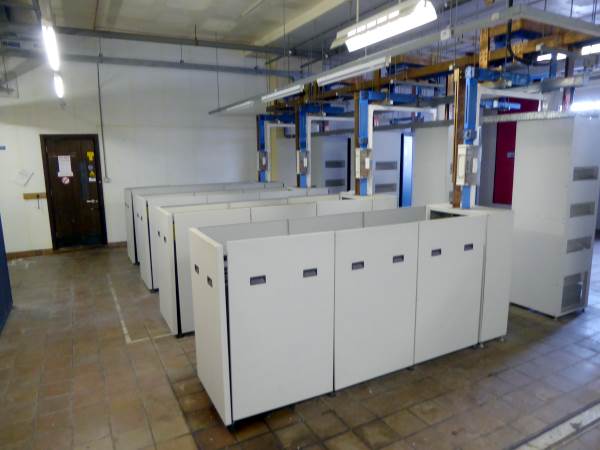
Below is a power room typical of an eighties installation, photographed in 2018 showing 4 battery cubicles, each cubicle has room for three layers of 24 cells. The busbar arrangement is clearer in the gallery Image 1. Three cubicles are fully equipped, as seen in Image 2 where the individual cells can be seen. The last has only two layers, so the battery to busbar connections are visible in Image 3. The installation has a total of 11 batteries in parallel. The copper busbar is the positive, earthed pole and the blue insulated busbar the 50 volt negative pole.
Modern Centralised Telephone Exchange Battery
The Emergency Switchboard ( EMSS) in the basement of this building has a single battery of similar fully sealed cells, laid out on two shelves that at one time would have held older Type 23 glass cells. It has its own separate power unit for its battery. There is a small separate standby generator too.
Power Unit [Rectifiers]
The power units, known in GPO / BT terminology as a 'Rectifier' converts medium voltage (240 / 415 volt) alternating current from the public mains supply into direct current at a nominal 50 volts to power the exchange load. The rectifier contains some means of regulating the output voltage so that the battery is kept charged, but not too high a voltage that the battery gasses.
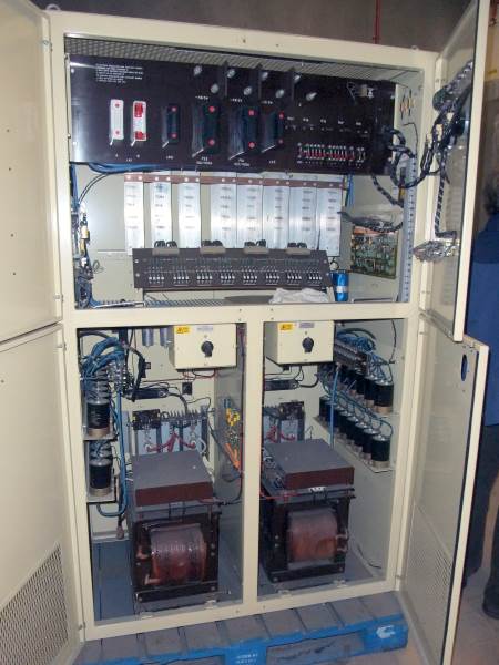
200 Amp Rectifier Unit
The photo above shows a rectifier unit with the inspection doors open. The two lower sections each hold a mains transformer and diodes and smoothing capacitors. The upper section contains the voltage regulator.
Depending on the load a varying number of rectifier units are provided. The exchange load depends on the number of calls in progress, lowest in the middle of the night and peaking in the mornings and again mid-afternoon. As the load fluctuates, the rectifier units are gradually switched into service.
In a centralised power exchange with sealed cell batteries, a power equipment rack is utilised. It contains a large number of relatively low current power units all connected across the common feed to the exchange busbar.
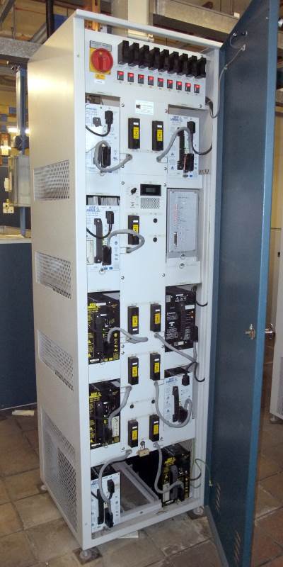
Power Equipment Rack
This rack is equipped with 9 power units, Rectifier 160 / 54 / 38A producing a nominal 54.9 volts at 38 Amps. A 2000 Watt output, all in a box 160 x 245 x 441 mm. The rack providing in excess of 300 amps. Four of these racks are provided at the 11 battery site, pictured in the section above.
The Images from BT Archives are Copyright BT Heritage, licensed under a Creative Commons License
 The Images from BT Archives are Copyright BT Heritage, licensed under a