This two part topic describes the second incarnation of the HANDEL Nuclear Attack Warning system and the carrier equipment known as Wire Broadcast System WB1400.
This second part of this topic, covers the distribution through the BT network to the customers local exchange then distribution from the final exchange to customers speech and siren receivers. The receivers themselves and their operating procedures. There is a section on BT test equipment used to maintain the system.
Part one described, the HANDEL control unit at A.D.O.C., Routine testing of HANDEL to the Carrier Control Point.
Carrier Control Area
Carrier Distribution within a District
Considerable changes were made in the way the carrier was distributed when WB1400 replaced the old system. Only the feed from the Carrier Control Point (CCP) to the Control Point Exchange (CPE) remained duplicated. The CPE control shelf selects one supply for further distribution around the network.
Duplicated distribution feeds were considered unnecessary as by the nineteen eighties most small exchanges were fed by underground cable, therefore less prone to faults. If an exchange loses its carrier feed, an exchange fault alarm is raised, previously this was only detected when customer's local call charging failed.
Usually there are a chain of exchanges, each feeding the carrier to the next. New features were introduced so the loss of incoming carrier at one exchange didn't cause false alarms at exchanges further along the chain.
Working Example
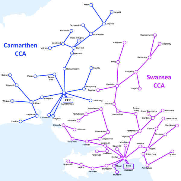
Here we use Carrier Area No. 036 Swansea and Carrier Area No. 037 Carmarthen to illustrate two adjacent distribution networks. These were surround by other areas at Haverfordwest and Cardigan, not shown on the map.
The Swansea Carrier Area comprised of Swansea Control Point Exchange (CPE) and 47 dependant distribution exchanges. The Purple coloured links in the enlarged diagram show the chain of carrier feeds radiating from Swansea CCP. In most cases the carrier is transferred between exchanges using phantom working over two pairs of wires. A description of phantom working is too technical for the scope of this page. Over the short distance between Mayals to Mumbles exchanges, only a single pair of wires was required to transmit the carrier.
South Wales Carrier Control Areas
On the six links shown in Blue in the enlarged diagram, the 72 kHz carrier could not be extended over the cable network as the losses were too high at the carrier frequency so they are sent as audio instead. At the feeding exchange, the carrier is demodulated to audio by a Unit WB 1400/6A. At the receiving exchange the normal carrier Pre-Amplifier (Unit WB 1400/2B) is replaced by a Local Oscillator / Modulator (Unit WB 1400/3A). The incoming audio modulates a locally generated 72 kHz carrier for distribution to its own customers and in the case of Llandeilo to feed the carrier forward to Dryslwyn, Talley and Llangadog exchanges, for further onward distribution.
To safeguard against the failure of the audio feed circuit, the /3A unit, monitors the 'G' tone sent every six hours by the CCP as part of the siren receiver test signal. If this is not received after 24 hours, an exchange prompt alarm is raised to alert maintenance staff.
The Carmarthen Carrier Area has the CPE and 26 dependant exchanges, with the carrier fed over two pairs between each exchange but no audio feeds. The map shows how exchanges along the boundary of the two areas are fed from their respective control point although cables may exist between those exchanges carrying normal telephone calls.
Carrier Distribution
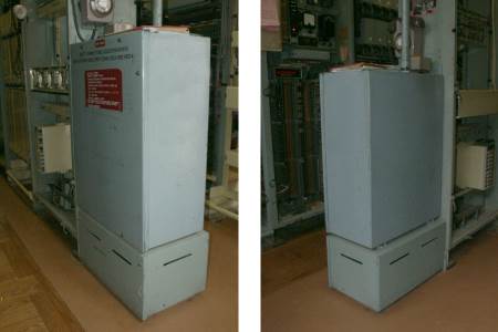
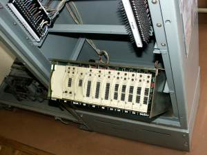
These photographs (taken at the Avoncroft Museum, Bromsgrove 15/07/04) show how the Equipment Carrier WB400A and Box Battery WB400A, formerly used for the WB400 system were modified to house the WB1400 distribution equipment. The cabinet is part of the exhibit of small rural dependent exchange 'UAX13' at the museum.
Cabinet Front and Back
The main cabinet is 1'-10½" wide, 1'-0½" deep, its height above battery box 2'-8". The
Battery Box is 1'-10½" wide, 1'-2" deep, 1'-11" high. Both are made of heavy gauge steel and are connected to the Main Distribution Frame via a conduit to protect the cables.
Removing the screws and lifting off the front cover reveals an Equipment Carrier WB1402, Diag. WB29604; Consisting of a shelf of slide in units which may be dropped forward to give access to the cards. In the enlarged view a strip along the bottom of the shelf indicates where the units fit. For example 4B is a Unit WB 1400/4B
The incoming carrier signal from the previous exchange enters the shelf via the Filter Unit which sends the signal to the pre-amplifier (Unit WB 1400/2B) Its output is connected to the inputs of up to three Distribution units (Unit WB 1400/4B). Each distribution unit further amplifies the carrier and provides 5 isolated outputs. The actual number of units fitted depends on the demand. Any of the 15 possible outputs can either be connected to outgoing junctions to feed dependent exchanges or used to supply warning point customers lines.
Shelf Schematic
According to demand, the shelf can be fitted with a maximum of five Local Line Units (Unit WB 1400/5A). Each card will supply up to two customers lines, either with the trickle charge for the Speech Receiver battery or to monitor the confirmation signal returned from the Siren Signalling Receiver in response to the automatic test signal sent by the CCP. Should the trickle charge fail (Line broken) or the confirmation signal not be returned from a siren control unit, a telephone exchange maintenance alarm is raised.
Power for the distribution shelf is normally obtained from the telephone exchange 50 volt supply. Should this fail the reserve battery is brought into use by the shelf Power Unit and Alarm Interface (Unit WB 1400/8B). Exchange fault alarms are raised through this interface should the incoming carrier fail or one of the local lines monitored by the /5A fail.
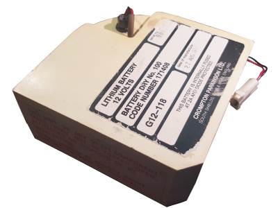
The reserve batteries and their Terminating Unit WB1403 are held in the battery box underneath the cabinet. One Battery Dry No. 100, is fitted for each Carrier Distribution Unit (Unit WB 1400/4B) on the shelf.
WB1400 Distribution Shelf
In lightly populated areas and islands, telephone exchanges may be served by radio links in the UHF or microwave range instead of copper pairs in overhead wires or underground cables. It is not possible send the WB1400 carrier over radio circuits or on very long lengths of underground cables found in rural areas which attenuate the carrier signal.
To overcome this problem, the serving exchange's shelf is fitted with a Audio Feeder (Unit WB 1400/6A) in place of the fifth Local Line unit /5A. This produces two audio outputs suitable for transmission over long cable routes or radio circuits.
At the dependent exchange, the normal carrier Pre-Amplifier (Unit WB 1400/2B) is replaced by a Local Oscillator / Modulator (Unit WB 1400/3A) which modulates a locally generated 72kHz carrier with the incoming audio signal which is distributed as normal by the rest of the shelf.
A few customers may be connected to their exchange by a long cable route unsuitable for transmission of the usual carrier. By special arrangement with BT Factories Division, carrier receivers would be modified by them to work with an audio input rather than carrier. After modification, they were designated as Receiver Speech WB1402 or WB1403 (in place of WB1400 or 1401 respectively) and Receiver Signalling WB1402 or WB1403 (in place of WB1400 or WB1401). These customers would be fed from the audio output from the /6A slide in unit.
$
Standby Power at Carrier Exchanges
UK telephone exchange apparatus is powered from a battery backed 50 volt supply derived from the mains supply. In larger exchanges, diesel generators provide a back up against a mains supply failure.
Exchange Power Supply
The 50 volt DC feed to the automatic telephone switching apparatus is supplied by a rectifier, or in larger exchanges a number of rectifier modules, with one or more batteries connected in parallel across the exchange load. These are kept charged by the rectifier modules. Should the mains fail, the batteries continue to run the exchange for a considerable period of time or until the generator, if provided, automatically starts. During the cold war period, sufficient diesel was stored to keep the generator(s) running for 28 days without replenishment.
During the cold war period, the small rural exchanges, Unit Automatic Exchanges (UAX) with 400 or fewer lines, did not have a standby generator. Due to their light load they could keep running for a number of days without mains power. In a post attack situation it is likely their exchange battery could fully discharge.
WB1400 Reserve Batteries
Each WB1400 cabinet has its own set of reserve batteries to guard against loss of the 50 volt DC exchange battery supply, due to the exchange battery completely discharging if the mains fails and the standby generator fails to start or breaks down. Unlike the rechargeable exchange lead-acid battery, the reserve batteries use lithium chloride technology which is not rechargeable. The reserve battery capacity is designed to last for 1000 hours.
At the Control Point Exchange (CPE) there will be at least two shelves, a CPE shelf and a distribution shelf. The CPE shelf is supplied from three batteries plugged into a Terminating Unit WB 1403. The distribution shelf has a separate set of batteries.
According to the number of outputs required there may be more than one distribution shelf at a CPE or at intermediate / distribution exchanges. Each shelf has its own separate battery backup with a separate Terminating Unit WB 1403 fitted with one battery per distribution amplifier (Unit WB 1400/4B) on the shelf. There will be at least one, with a maximum of three amplifiers per shelf and hence a maximum of three batteries in parallel per terminating unit. The reserve batteries only supply enough power to operate the carrier distribution function but not the trickle charge for the speech receivers, these rely on their own internal rechargeable battery to keep functioning.
WB1400 Cabinet Standby Power
Each Lithium battery measures 13 cm x 13 cm and 6 cm deep, known by B.T. as a Battery Dry No. 100, its rated as 12 volt 20 Ampere Hours. The Terminating Unit WB 1403 has three battery connectors and an electro-chemical elapsed time indicator (Indicator WB 1400) scaled in 0-1000 hours. These items are featured in the photo gallery.
$
Local Distribution to Warning Points
Wiring of Warning Points
To provide a customer with WB1400 service,their exchange line circuit is routed via the trickle charge feed and monitor unit, then out to line. A carrier supply from one of the fifteen outputs from the three distribution amplifiers is wired across these same line connections. A filter within the monitor and trickle feed unit prevents the carrier being shunted by the customers exchange equipment.
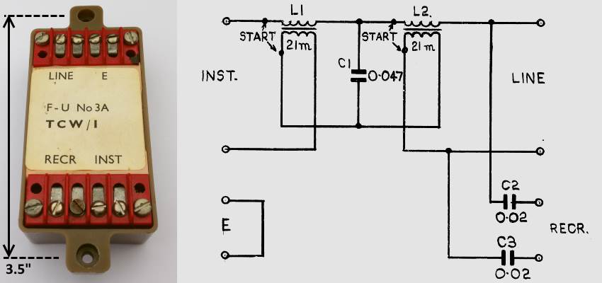
At the customers premises, a Filter 3A is used to block the carrier from the telephone instrument. The RECR terminals on the filter that were used for the earlier system's receiver are left disconnected as they are isolated from the direct current on the line by C2 & C3. The WB1400 Carrier Receiver is connected directly to the line so it may receive the carrier and to trickle charge its battery.
WB Filter Unit 3A and its Circuit Diagram WB28680
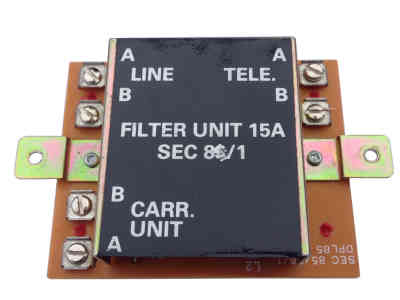
For new installations at premises not already having a WB receiver, the Filter Unit 15A pictured here without its case, supersedes the older 3A. The new design gives better sidetone performance on the associated telephone.
Filter Unit 15A
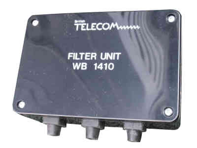
A special Filter Unit WB1410 is used at ROC Posts to handle the four wire circuit feeding the TeleTalk device.
Filter Unit WB1410 Diagram WB29747$
At the ROC Post, the Teletalk AD8010 employs two pairs of wires, the first pair carries the speech from the Teletalk. The second pair carries the speech towards the teletalk but is intercepted via a Filter Unit WB 1410 to separate the carrier. The speech and power is sent towards the Teletalk via the line terminating unit.
Block Terminal : BT Case 200
The line terminating unit is contained within the light grey box known as a Case 200, seen here with a block terminal, both are mounted on the same backboard as the filter, receiver and loud speaker.
Simplified ROC Post Wiring
The terminating unit returns the power back to the filter's POWER terminals where it merges with the separated carrier and outputs at the filter's RECR terminals. This allows the receiver to trickle charge its battery.
WB1400 and WB1401 Warning Receiver
The two models of speech receiver are essentially the same, the only difference being an internal strap to control how many 'W' signals are required to turn the speaker on. The Carrier Control Point (CCP) described in Part 1, can choose to broadcast an 'Alarm' or 'Call' message to 'ALL' users or just the 'SELECT' group of users. Discrimination is made by preceding the message with either Four pulses of 'W' signal to turn on only the select group or Eight pulses to turn on every receiver in the area. A 'W' tone pulse is 115mS of 605Hz tone separated by a 115mS interval.
Receiver Speech WB1400$
Receiver Speech WB1401 [Select Group]
The ROC & UKWMO locations were fitted a Receiver Speech WB1401 forming a 'SELECT' group which enabled the police to broadcast peacetime exercise messages without affecting the general users who may have accidentally left their receiver switched on. As this responds to four or eight pulses of 'W' tone, it will receive messages sent to either the 'SELECT' and 'ALL' groups of user.
Receiver Speech WB1400 [General User]
All other locations had a Receiver Speech WB1400 fitted. This requires eight pulses of 'W' tone to enable the speaker and therefore will only receive messages sent to 'ALL' users. This is the most commonly found version of the carrier receiver.
Power Supply
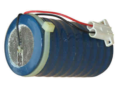
With reference to the speech receiver's photo gallery, The lower printed wiring board contains the loud speaker's power amplifier and 'W' signal detection logic. The upper circuit board demodulates the 72kHz amplitude modulated carrier and controls the trickle charging. When the host telephone line is not in use, a small current trickle charges the receiver's internal battery, a 12 Volt 1 Ah, rechargeable NiCad (a Battery Secondary No. 32) this blue canister (50mm Diameter, 95mm Long) sits in the lower section of the receiver casing.
Battery Secondary No. 32
Message Format and Monitor Tone
Once the receiver speaker is activated by the appropriate number of 'W' signals, the user will hear a 6.4 second blast of 'Alarm' or 'Call' signal preceding the spoken message. The speaker remains active during the 'Alarm' or 'Call' signal and throughout the voice message, then mutes after a 20 second delay. The CCP turns off the 'Speak Now' light and reconnects the monitor tone 7 seconds after its speak button is released. Users will hear the monitor tone during the 20 second delay before their speaker is muted. The user would not normally hear the 'W' signals unless the CCP initiates a subsequent message before the speaker is muted.
Monitor Tone (Confidence Tone) is a slow, soft pip tone of 1100Hz of 50mS duration repeated every 1600mS, generated while the CCP is idle and not sending speech broadcasts or siren control tone signals, it restarts once the message or signal has finished. It can be heard at any time by operating the test switch on the loudspeaker unit, its purpose is to give the recipient confidence their receiver is working.
I have had queries from people who incorrectly thought the tone went off after the Attack Warning and came back on after the All Clear. NO - It is always present when the system is functioning but not broadcasting a message or siren control signal.
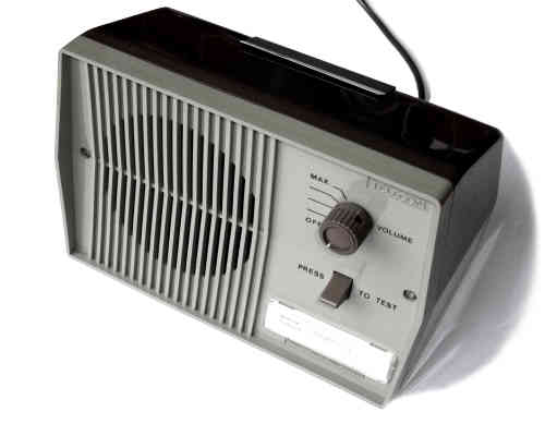
Loudspeaker Units
Two different types of loudspeaker unit may be connected to a receiver. The 'Loudspeaker Unit WB1400' was suitable for office type environments. The clip on the top of the speaker retains the user instruction card (Label 585A item code 374170) which is shown in the gallery.
Loudspeaker Unit WB1400$
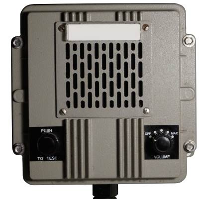
The other design of speaker, is the ruggedised 'Loudspeaker Unit WB1401' fitted in ROC posts or other damp and harsh areas such as factories.
Loudspeaker Unit WB1401
WB1400 Warning Point User Instructions
Instruction Booklet
In Derbyshire, Warning Point operators were provided with a twelve page manual describing the function of the U.K.W.M.O. and giving detailed instructions on testing the receiver and ultimately what to do in a war situation. It covers the use of the siren, maroons and radiac monitoring unit.
This booklet is far more informative than the little card that clips behind the loudspeaker unit and well worth taking the time to read for an insight into what was expected of a warning point operator.
The gallery contains a scan of the booklet kindly provided by R o d d y B u x t o n. He was given it by the BT Engineer recovering the WB1400 receiver from Courtaulds in Spondon, where he was working at the time.
$
Power Siren Control Signals
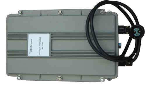
Siren Signalling Receiver$
Externally the siren control equipment known as a 'Receiver Signalling' looks almost identical to the 'Receiver Speech'. The receiver demodulates the 72kHz carrier and filters out two control tones known as 'G' the guard signal and 'S' the siren signal. The receiver is unaffected by speech broadcasts as they do not imitate the guard signal. These two control signal frequencies and their duration remained the same as the superseded system.
There are two variants of the receiver only differing by the type of guard signal they respond to, a 'Receiver Signalling WB1400' for Civil Defence sirens requiring a 'G' signal (1500Hz) pulsed 400ms On / 400mS Off twelve times, to prime the logic to accept the 'S' signal (2160Hz) to energise the siren motor. A 'Receiver Signalling WB1401' for Flood Warning Sirens, is primed by a 'G' signal pulsed 115mS On / 115mS Off, twelve times before the 'S' signal starts. In response to the 'S' signal, the receiver sends out a low current mains voltage signal into the Home Office provided Siren Switch Panel, where it operates a powerful relay to energise the siren motor. The duration of the 'S' signal in either receiver determines how long the siren motor is energised.
The signalling receiver has a four pin plug connecting to the siren switch panel over which it derives its mains supply and returns a siren energise signal. There are no reserve batteries in this receiver as they unnecessary because the siren is mains powered without any reserve supply. The Home Office Switch Panel is described in the dedicated 'Power Siren' page on this website.
The siren signalling receiver is designed to be automatically self tested by signals sent by the CCP which generates alternately a 'Test On' and 'Test Off' signal at 6 hour intervals. In response the receiver applies a signal to the line which is detected in the carrier distribution cabinet at the local telephone exchange. Should the receiver not respond to the self test due to faulty electronics or the connecting phone line has become faulty, a telephone exchange maintenance alarm is raised. This automatic self testing represents a huge improvement on the previous system, that was only tested six monthly and required a police visit to each siren point to check a test lamp was glowing and then reset it.
Special Cases Preventing Fault Monitoring from the Local Exchange
This topic describes the special cases where fault monitoring by the serving telephone exchange is not possible. An extra piece of equipment is necessary to supply the power for the receiver and in the case of a siren, to raise a local alarm should the self test fail.
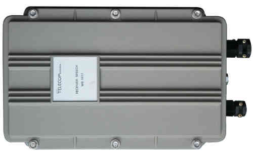
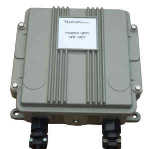
Receiver Mains Power Unit$
The speech receiver is normally powered from the telephone line but under some circumstances this was not possible, such as when a signalling receiver shares the same phone line, or in rarer cases such as a high voltage substation or power station. In these situations the receiver battery is charged from the mains supply using a Power Unit WB1401A pictured here. The power unit incorporates a carrier filter too. The exchange does not supply the receiver power and cannot monitor for faults, it is known in BT terminology as a 'Locally Powered Speech Receiver'. Faults would only become apparent during police routine test broadcasts from the CCP.
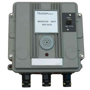
Siren Monitor Unit$
When circumstances dictate that the signalling receiver cannot be directly connected to an external telephone line the fault monitoring must be carried out locally. The Monitor Unit WB1400 checks the signalling receiver responds to the CCP's 6 hourly test signals and incorporates a carrier filter too. In BT terminology this is a 'Locally Monitored Signalling Receiver'.
If the monitor unit detects a fault, it sounds a buzzer and the red LED glows, the buzzer can be stopped with the 'REC ATTN' key (Receiving Attention) and the fault is reported to BT. But this requires the unit to be in a manned office.
If the monitor unit cannot be sited in a manned office, it can be wired to extend the alarm some distance into the building's telephone switchboard room, so the operator can report the siren receiver faulty to BT.
Test Equipment
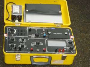
Tester WB1401A
Tester WB1401A
Roy has kindly sent this photograph of a Tester WB1401A from the Belfast ROC Museum. This multi function test box can simulate the Carrier Control Point ( CCP ) and also monitor the actual WB1400 carrier as it passes through the various parts of the network from the CCP to the Receiver.
$
In simulation mode, it generates a carrier modulated by the control signals 'call all' 'call select' 'attack' 'flood' generated by a CCP to alert speech receivers and sound both air raid and flood sirens, allowing the receivers to be functionally tested. It will also simulate the exchange power feed to the receiver battery. In monitor mode, it serves as a Level Measuring Set ( LMS ) for both audio and 72kHz carrier in the range of -60 to +20 dB. It will also monitor the demodulated audio on the carrier being received by the LMS and the test signals generated by the CCP simulator. This actual unit was manufactured in 1984 to diagram WB 29754, its dimensions are 45 x 26 cm.
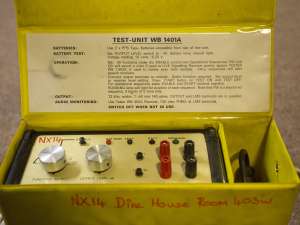
Test Unit WB1401A
Test Unit WB1401A
This test unit is a cut down version of the Tester WB1401A, providing only a modulated carrier output for testing both Civil Defence and Flood Warning (FW) Receiver Signalling. Monitoring and Level Testing is performed with the old Tester WB400A. I'm indebted to Gavin for sending the photograph.
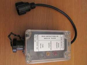
Tester WB1403A
Tester WB1403A
In the lid of the Tester WB1401A and in the carrying case of a Test Unit WB1401A is a further small test unit used when testing Signalling Receivers allowing a functional test to be performed without sounding the siren. The Tester WB1403A is connected into the mains wiring of the signalling receiver and has lights to indicate mains is present and when the siren would operate. The tester prevents the actual operation of the contactor relay that applies the 3-Phase mains supply to the siren motor. Adrian has kindly supplied this photograph.
$
Carrier Control Point Tester / Simulator
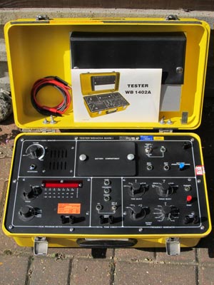
Tester WB1402A
Adrian's picture shows the Tester WB1402A used for various tests in the Control Point Exchange (CPE) and Carrier Control Point (CCP). The tester is in four sections, an Audio Monitor allows the engineer to listen to the speaking clock on the incoming HANDEL lines at both the exchange and CCP.
The section below is a peak program meter which displays the maximum level of the audio. This is used to set up the correct level of the speaking clock so it is neither too loud or too quiet. The audio volume of the person giving the attack warning message, is set at the A.D.O.C. in relationship to the level of the speaking clock, thereby ensuring the message will be clearly received at the Police station.
$
At the bottom right is an audio frequency generator with four preset output tones P, Q, P+Q and 180Hz with five differing durations to check the equipment at the CPE and CCP will only respond to the correct length of the appropriate tone signal. The P tone is 1200Hz and Q tone 1440Hz which are in the normal audio spectrum, to prevent misoperation from the speaking clock or test messages, the duration of the combined tones is important.
The lower centre section allows the 180Hz signal sent from the CPE to the CCP to be checked for the correct level, duration and frequency tolerance.
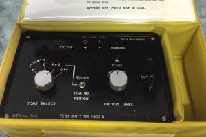
Test Unit WB1402A
Test Unit WB1402A
The Test Unit WB1402A, is a scaled down version of the Tester 1402A only able to generate the P and Q tones. Their signal level has to be set using a separate level measuring set. It would be used at the exchange (CPE) but not the CCP


 This page is Copyright © RINGBELL.CO.UK, under a


