When customers lines and junctions between exchanges were carried on open wires, there was a risk of electrical contact with mains electricity wiring, tram wires and lightning strikes. Various measures were used to protect the equipment. As the risk diminished as customers lines became a single span of insulated dropwire from pole to house or underground fed, the fault prone protective devices were replaced with dummy units.
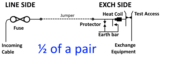
Line Side Protection
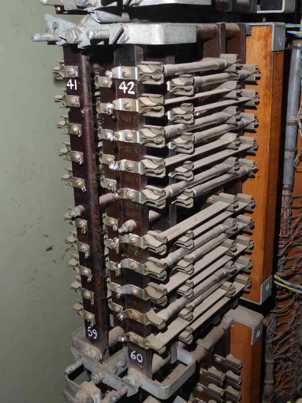
In this photograph of a Fuse Mounting 4028, the top pair (42) is fused with slow acting Fuse 28B rated at 200mA, the pair below (44) is fitted with solid brass dummy fuses, the sequence of real fuse / dummy is repeated down the line of even numbered pairs for demonstration purposes. The original quick acting fuses were made of two paxolin pieces between the end contacts and a central flimsy asbestos tube containing the fuse wire rated at 2 amps.
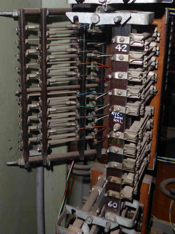
To allow jumpers to be connected to the front solder tags, the fuse mounting may be opened as shown. The incoming cables connect to the rear tags.
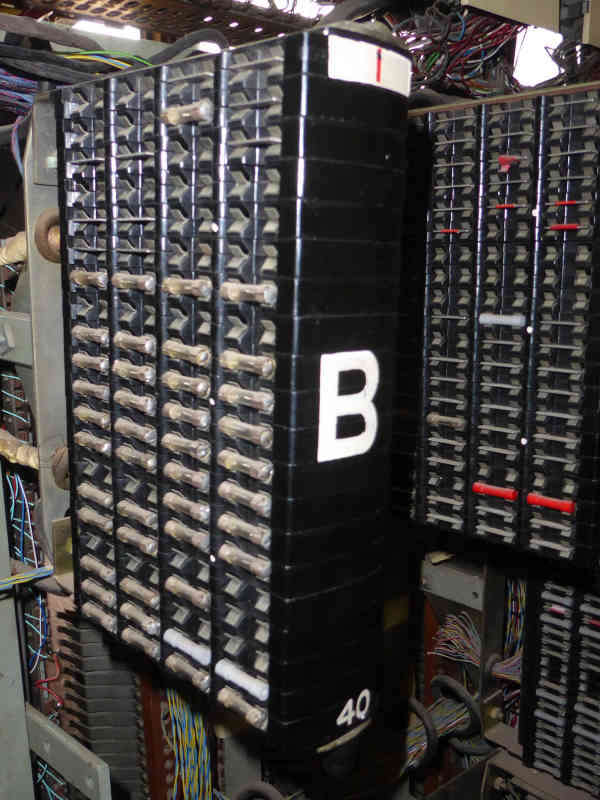
In the 1960s a more compact Fuse Mounting No. 8064 allowed 40 pairs to be terminated. Pairs may be fitted with delayed action fuses or dummies. There are a mixture of types in this photo, glass fuses, grey dummies, flat metal dummies. Important high grade circuits have red tubular or red marked flat plate dummies.
Exchange Side Protection
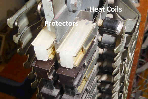
This is the top section of a strip of 20 Protectors, Heat Coil and Test (Prot. HC & Test). The top four circuits have heat coils, but circuit five has dummies. The top protector is clear polythene, the one below is a dummy and the one below that is a black polythene variety.
Over Voltage Protection
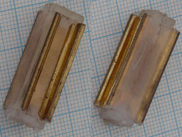
The normal working voltage on a telephone line is 50 volts DC, but may rise to 75 volts AC during ringing. To prevent damage to the equipment by higher voltages, from contact with power lines or lightning strikes, protectors were employed. The original design of protector consisted of two graphite blocks with their opposing faces coated in a hard varnish, designed to withstand 250 volts but breakdown above 500 volts. These were superseded by a single part moulded polythene type containing a fixed air gap which proved more reliable. Shown here on 1 mm graph paper.
One side of each protector is earthed and the other connected to either the 'A' or 'B' wire of the circuit. If an overvoltage fault causes the protector to spark over, the current flowing causes the line fuse to rupture.
Over Current Protection
Over current protection was originally provided by a fuse on the line side rated at 2 amps. To prevent damage to the equipment by a sustained current less than 2 amps, a heat coil was used. With the introduction of slow acting fuses rated at 0.2 Amps, heat coils became redundant and dummies were fitted.
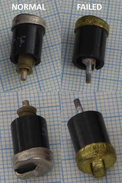
The heat coil consists of a bobbin wound with nickel-silver wire with a resistance of 4 ohms, soldered with special low melting point solder to a pin. The device is designed to withstand 350 mA for 3 hours, but fail within 3.5 minutes when passing 500 mA. The heat coil is compressed between two springs, when subject to a fault current, the heat generated melts the solder allowing the bobbin to slide up the pin, as seen on the left hand photos. This causes the line to be earthed and at the same time disconnecting the exchange equipment from the line.
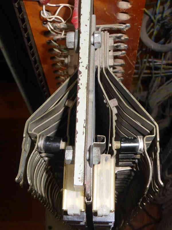
The final photograph shows the complete Heat Coil and Test assembly. The outer set of springs on each side are for plugging in the line tester or fitting insulated wedges to temporarily disconnect a faulty line. If a heat coil fails, it collapses inward opening a gap in the outer set of springs, disconnecting the exchange equipment.